


Quattro DC User Switches C1
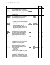
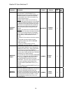
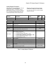
The tracking delay shown is defined as
(1/RESPONSE) seconds. The tracking delay
is not effected by the gain reduce multiplier.
The inner loop crossover parameter (INNER
LOOP XOVER(A1)) should not need to be
changed. But if the number is changed, it
must satisfy the following formula:
The PI Speed Regulator is tuned by:
• System Inertia parameter (INERTIA(A1)),
which is easy to obtain by using the drive
software to estimate the system inertia.
The Ramp Down Enable has the following
three possible sources:
• An input logic bit (EXTERNAL TB)
• Response parameter (RESPONSE(A1)),
which is the overall regulator bandwidth in
radians per sec. This parameter defines
the responsiveness of the speed regulator.
multiplier
reduce
gain
response
crossover
loop
inner
×〈
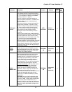
PI Speed Regulator
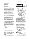
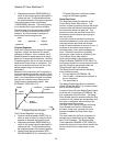
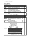
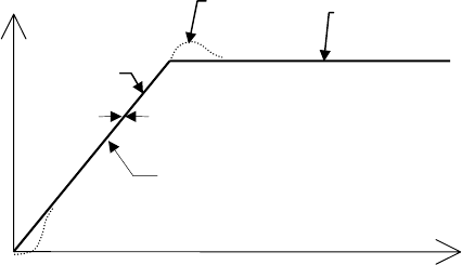
When the Proportional plus Integral (PI) speed
regulator is used, the response to a speed
reference is different. As an example, the PI
Speed Regulator’s speed response is shown
below for a ramped speed reference. With the
PI speed regulator, the end of each accel and
decel period, there will be an overshoot. The
amount of overshoot will be a function of the
defined phase margin and response
parameters.
Because of this overshoot, the PI regulator is
not recommended for elevator control by itself.
However, the PI regulator is the proper choice
when a live torque demand signal is available
from the car controller as an always-active
Feed-Forward compensating signal. See
EXTERNAL TORQ SRC (C1).
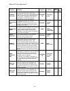
PI Speed Regulator Example
• Response parameter (RESPONSE(A1)),
which is the overall regulator bandwidth in
radians per sec. This parameter defines
the responsiveness of the speed regulator.
• Speed Phase Margin parameter (SPD
PHASE MARGIN(A1)) is used only by the
PI Speed Regulator to define the phase
margin of the speed regulator.
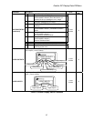
Ramp Stop Select
This parameter allows the selection of the
Torque Ramp Down Stop function. This
function is used to gradually remove the torque
command after the elevator has stopped and
the mechanical brake has been set. This
prevents a shock and possible ‘bump’ felt in
the elevator from the torque signal going to
zero too quickly.
A function unique to elevators involves the
interaction between the motor torque and the
mechanical brake that holds the elevator.
Under full load conditions at the end of a run, if
the brake is set and the motor torque is
removed quickly, some brake slippage may
occur. Therefore, the option of gradually
reducing the motor torque is provided by the
Torque Ramp Down Stop function.
Upon being enabled by the Ramped Stop
Select Parameter (RAMPED STOP SEL(C1)),
the torque command is linearly ramped to zero
from the value that was present when the
‘Ramp Down Enable’ was selected.
• The run logic – initiated by the removal of
the run command
• The serial channel
The Ramp Down Enable Source parameter
(RAMP DOWN EN SRC(C1)) is used to select
one of the above options.
speed
feedback
zero tracking delay
speed
reference
commanded
speed
overshoot
time
speed
A method of providing the Ramp Down Enable
would be with a logic signal (EXTERNAL TB)
that is dedicated to that function. The Ramp
Down Enable would be asserted while the Run
command is still present and remain there until
the ramp is completed, after which the Run
command would be removed.
The RUN LOGIC option to trigger the Ramp
Down Enable from the Run command is
provided. In this case, removal of the Run
command enables the Ramp Down Stop
Function.
The time it takes for the Drive to perform its
ramped stop is determined by the Ramped
Stop Time Parameter. The Ramped Stop
Time parameter (RAMPED STOP TIME(A1))
selects the amount of time it would take for the
drive to ramp from the rated torque to zero
torque.
60