


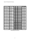

Quattro DC Line Side Power Convert A5 Submenu
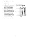
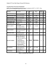
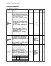
Line Side Power Converter A5 submenu
NOTE: The only parameter that should ever need to be adjusted is INPUT L-L VOLTS. Other
parameters are for Magnetek Engineering use only.
Run
lock
out
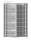
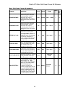
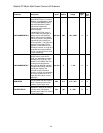
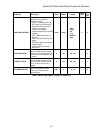
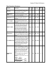
Parameter Description Units Default Range
Hidden
Item
Id REG PROP GAIN
Proportional gain for out-of-
phase current regulator
none 0.30 0.00 – 9.99
N N
Id REG INTEGRAL GAIN
Integral gain for out-of-
phase current regulator
none 10 0 – 999
N N
Iq REG PROP GAIN
Proportional gain for in-
phase current regulator
none 0.30 0.00 – 9.99
N N
Iq REG INTEGRAL GAIN
Integral gain for in-phase
current regulator
none 40 0 – 999
N N
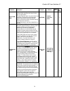
DC BUS REG P GAIN
Proportional gain for bus
voltage regulator
none 3.00 0 – 9.99
N N
DC BUS REG I GAIN
Integral gain for bus voltage
regulator
none 40 0 – 999
N N
INPUT L-L VOLTS
(Input Line to Line Voltage -
Input Voltage)
This parameter sets the
input voltage or AC line
input voltage to the drive.
volts 480 110 – 552
N Y
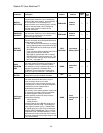
DC BUS V BOOST
(DC bus voltage reference)
Adjusts the DC bus voltage
boost above the peak of
line voltage.
Vdc 30 15 – 75
N N
SW BUS OV LEVEL
(Software Bus Overvoltage
Level) DC bus software
Overvoltage trip point.
Vdc 850 100 – 850
N N
BUS VREF SOURCE
(Bus Voltage Reference
Source) Selects the bus
voltage boost reference.
• Track Line V uses the
actual line voltage for the
bus reference.
Recommended for
systems with a stiff line.
• Trk Vin Param uses
INPUT L-L VOLTS (A5)
for the bus reference.
Recommended to
systems with a soft line.
none
Trk Vin
Param
1= Track Line V
2= Trk
Vin Param
N N
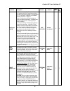
PLL FILTER FC
(Phase Locked Loop Filter
Frequency) Utility line
Phase Locked Loop filter
corner Frequency
Hz 40.0 0.0 – 150.0
N N
LS PWM FREQ
(Line Side PWM
Frequency) Converter
PWM Freq
kHz 10.0 2.5 – 16.0
N N
Table 8: Line Side Power Convert A5
46