


Quattro DC Drive Sequencing
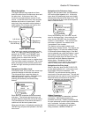
c. Pre-charge contactor PCM is then
pulled in. This provides resistor limited
inrush current to DC bus capacitors
from AC mains and separate rectifier.
ABNORMAL Operation Sequence
1. If a Drive or Drive Sequence Fault occurs
the Drive will immediately open the motor
contactor, de-energize the Brake Pick,
Brake Hold, and Drive OK Relays if so
programmed. May be caused by:
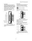
3. DC bus is Pre-Charged
a. With pre-charge contactor PCM closed,
separate resistor and rectifier circuits
limit capacitor charging inrush current.
a. “Fatal Error” drive Faults including loss
of serial communications
b. Bus voltage is monitored during pre-
charge to verify proper voltage build-up.
(See 6.a. below)
b. Opening of the contactor power Safety
circuit while the contactor is pulled in
c. Loss of correct motor contactor or
Brake Relay feedback.
c. Target bus voltage is nominal input
VAC (INPUT L-L VOLTS (A5)) X √2.
2. If an Alarm occurs, the drive will signal an
Alarm but continue to run. May be caused
by:
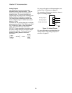
4. Mains contactor is closed
a. As measured DC bus voltage nears
target value main utility power contactor
UTM closes.
a. Drive Alarms including motor overload,
drive over temp warning
b. Aux contact feedback from UTM
indicates to controls that main utility
contactor is closed.
b. Loss of correct feedback from Brake
Hold relay or Brake Switches
c. Open motor thermostat circuit
c. Then Pre-charge contactor PCM is
opened. (See 6.b. below)
d. Speed command is held at zero due to
conflict with the analog speed
command polarity and the run up/ run
down logic
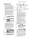
5. Boost converter is turned ON.
a. DC bus voltage is boosted to a higher
level as programmed by the Boost
Level parameter setting in order to
achieve near unity power factor and low
harmonic content of the Quattro drive.
e. Encoder Fault (C1) set to disabled
f. The drive is or was being limited by
the motor torque limit setting (Hit
Torque Limit)
b. Motor field controls also turn ON to
begin regulating motor field current
and/or operate main motor armature
circuits.
g. Speed feedback is failing to properly
track the speed reference (Speed Dev)
h. DC bus voltage drops below user
specified percent of the input line to
line voltage
c. The boost converter will remain ON as
long as any field or armature current is
being provided to the motor. (See 6.c.
below) Time-out of the DSPR (Drive
Stand-by Power Reduction) feature or
other command may turn the Boost
converter OFF when drive is idle
although standby field will still be
present. In that case as new pre-
charge cycle must occur before drive
re-start.
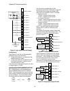
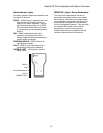
Quattro Pre-Charge
When power is first applied to the Quattro
drive, or after it has shut itself down via a
DSPR time-out, the internal DC bus must be
pre-charged before operation can resume.
The following sequence will occur:
1. Power is applied to the Quattro drive
a. Control power may be applied before or
after 3-phase main power
b. Some OEM drive versions may have a
built-in control transformer
6. Problem prevention
a. If DC bus voltage does not rise at the
expected rate to the expected voltage
level during pre-charge a “Charge
Fault” is declared.
c. Drive controls should become active
but no contactors should operate
2. Quattro drive receives command to
‘energize’
b. UTM and PCM are interlocked with aux
contacts such that UTM cannot be
picked unless PCM is already closed.
Once picked, an aux contact of UTM
seals the same circuit allowing PCM to
be dropped with UTM remaining ON.
a. This command may be from serial link
software or hardware logic command to
deliver motor field current in
preparation to start.
b. AC input voltage from mains is
measured and verified to be adequate
according to the setting of the VAC-
input adjustment parameter.
c. In the event of a major drive Fault, UTM
will be opened to disconnect utility lines
from main power devices of Quattro.
22