


Quattro DC Drive Parameters A1
Parameter Description Units Default Range
Hidden
Item
Run
lock
out
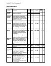
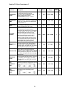
OVERSPEED
LEVEL
(Over speed Level)
Sets the percentage
of rated speed the drive uses (in
conjunction with OVERSPEED TIME,
below) to determine when an
OVERSPEED fault occurs. Units in
percent of contract speed
% 115.0 90.0 – 150.0
Y N
OVERSPEED
TIME
(Over speed Time) Sets the time that the
drive can be at or above the OVERSPEED
LEVEL (A1), before the drive declares an
OVERSPEED FLT.
sec 1.00 0.00 – 9.99
Y N
OVERSPEED
MULT
(Over Speed Multiplier)
Sets the
percentage of CONTRACT CAR SPD (A1)
for the OVERSPEED TEST (U4).
% 125.0 100.0 – 150.0
Y N
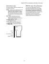
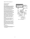
ENCODER
PULSES
(Encoder Pulses per Revolution, PPR)
T
his parameter sets the pulses per
revolution (per channel) the drive receives
from the encoder. Set this value to agree
with the pulses per revolution on the
encoder nameplate if the tachometer is
directly coupled to the motor shaft. If
tachometer connected to rider roll to
measure linear velocity, then this should
be a calculated value equal to the counts
expected from the encoder when the
motor makes exactly one revolution.
PPR 5000 600 – 10000
N Y
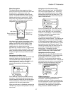
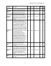
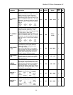
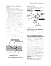
SPD DEV LO
LEVEL
(Speed Deviation Lo Level) Range around
the speed reference for speed deviation
low logic output. Units are in percent of
contract speed. See SPD DEV LO LEVEL
and SPD DEV HI LEVEL on page 37.
% 10.0 0.1 – 20.0
Y N
SPD DEV TIME
(Speed Deviation Time) This parameter
defines the time the speed feedback
needs to be in the range around the speed
reference defined by SPD DEV LO LEVEL
(A1) before the Speed Deviation Low logic
output is true.
sec 0.50 0.00 – 9.99
Y N
SPD DEV HI
LEVEL
(Speed Deviation High Level) Level for
declaring speed deviation alarm. Units are
in percent of contract speed. See SPD
DEV LO LEVEL and SPD DEV HI LEVEL
on page 37.
% 10.0 0.0 – 99.9
Y N
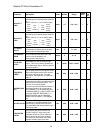
SPD
COMMAND
BIAS
(Speed Command Bias)
This parameter
subtracts an effective voltage to the actual
analog speed command voltage signal.
uses
software
drive
signal
MULT
COMMAND
SPD
BIAS
COMMAND
SPD
voltage
input
channel#1
analog
=×
⎟
⎟
⎟
⎠
⎞
⎜
⎜
⎜
⎝
⎛
−
volts 0.00 0.00 – 6.00
Y Y
SPD
COMMAND
MULT
(Speed Command Multiplier) This
parameter scales the analog speed
command.
uses
software
drive
signal
MULT
COMMAND
SPD
BIAS
COMMAND
SPD
voltage
input
channel#1
analog
=×
⎟
⎟
⎟
⎠
⎞
⎜
⎜
⎜
⎝
⎛
−
none 1.00 0.90 – 5.00
Y Y
32