Quattro DC Troubleshooting
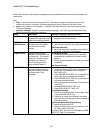
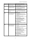
Name Description
Possible Causes & Corrective Action
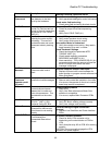
Field
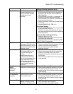
Overcurrent
An over current condition has
been detected in the field
circuit by the hardware.
Check Parameter Settings
Verify parameter settings for motor field control
Check motor field and wiring
Check motor field and wiring for short circuits
Full Fld Time
Drive was commanded to
provide Full Field current but
not told to Start for longer than
the time set in FULL FIELD
TIME (A1)
Incorrect Start Timing
Check for proper drive Start sequencing
signals
Verify FULL FIELD TIME (A1)
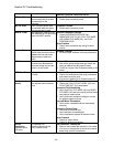
Hit Current Limit
(alarm)
The drive is or was being
limited by the motor current
limit setting. This can limit
acceleration rates and cause
subsequent velocity tracking
errors.
Incorrect Wiring
Verify motor armature circuit wiring
Verify motor field current is correct
Drive and/or Motor is Undersized
Verify drive and/or motor sizing. May need a
larger capacity Drive and / or motor.
Check Parameter Settings
Check the torque limit parameter MTR
TORQUE LIMIT (A1)
Check speed regulator parameters
RESPONSE and INERTIA (A1)
Alarm sensitivity - TRQ LIM MSG DELAY (A1)
parameter determines the amount of time the
drive is in torque limit before the alarm
message is displayed.
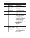
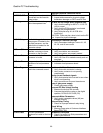
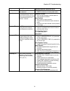
HW/SW
Mismatch
Line side software is installed
in the motor side control
board.
Incorrect Software in Motor Side Board
Replace A2 board with correct software for
board location or program correct software into
Motor Side Board
Invalid
Checksum
(operator serial
link error)
The operator received four
consecutive invalid messages.
Noise or Bad Connector Connection
Remove and re-seat the operator in its cradle.
If re-occurs, the operator or the drive’s control
board may need to be replaced.
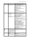
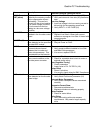
IP Comm
A fault has occurred in the
communications channel
between the Line side and
Motor side processors. This
was detected on the motor
side.
Communication problem
Reset drive
Verify Line Side software and Motor Side
software is compatible.
If re-occurs, replace Main Processor PCBs
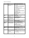
Line HI Volts
Line voltage is greater than
552 VAC. (480 x 115%)
Monitored via the DC Bus.
Line Voltage is too High
Verify DC Bus is reading voltage correctly
Verify Line voltage is set correctly
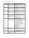
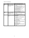
LS A to D
The Analog to Digital
conversion on the line side
control board is not working
properly.
Line Side Analog to Digital Conversion
incorrect
Replace Line Side Main and Power Interface
PCBs
LS AC CNTCR
The main AC power contactor
is not following the
commanded state within 1
second.
AC Power Contactor Problem
Check for faulty UTM contactor coil or
interlocking aux contact blocks on PCM or
UTM
Verify that pilot relay K2 on PCB A8 is working
properly
CAUTION: Do not manually engage the UTM
contactor with power applied.
85


