


Quattro DC Drive Parameters A1
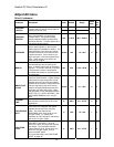
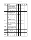
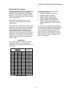
SPD DEV LO LEVEL and SPD DEV HI
LEVEL
(Speed Deviation Low / High Level)
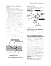
These two functions are available to indicate
how the speed feedback is tracking the speed
reference.
• Speed Deviation Low – indicates that the
speed feedback is tracking the speed
reference within a defined range.
• Speed Deviation High – indicates that the
speed feedback is failing to properly track
the speed reference.
The Speed Deviation Low function has the
ability to set a configurable logic output
. The
logic output will be true, when the speed
feedback is tracking the speed reference within
a defined range around the speed reference
for a defined period of time (see Figure 13).
The defined range is determined by the Speed
Deviation Low Level parameter (SPD DEV LO
LEVEL) and the defined time is determined by
the Speed Deviation Time parameter (SPD
DEV TIME).
The Speed Deviation High function
annunciates a Speed Deviation Alarm
, and has
the ability to set a configurable logic output
.
The alarm will be annunciated and the logic
output will be true, when the speed feedback is
not properly tracking the speed reference and
is outside a defined range around the speed
reference (see Figure 13). The defined range
is determined by the Speed Deviation High
Level parameter
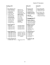
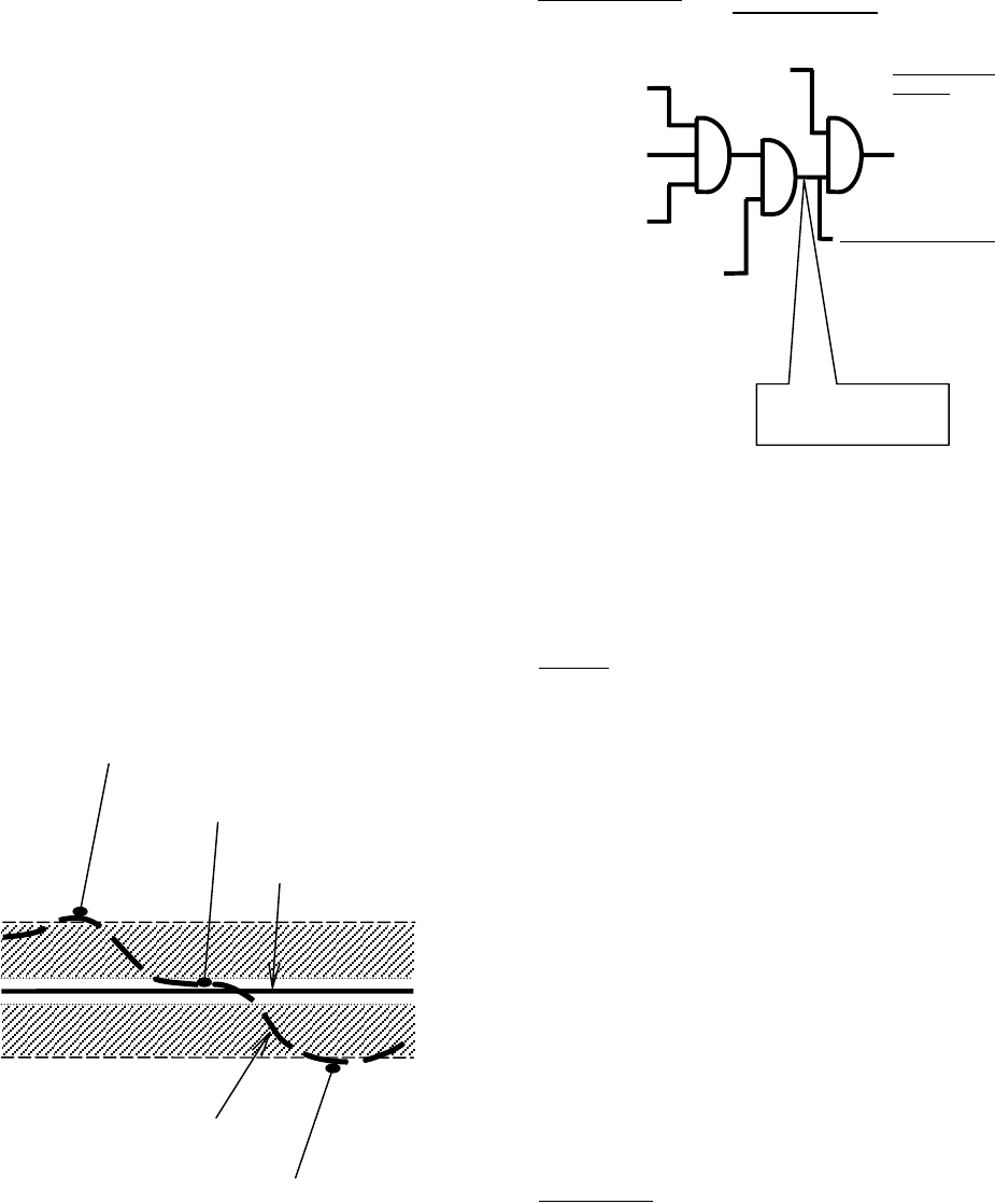
Figure 13: Speed Deviation Example
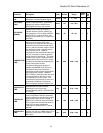
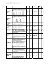
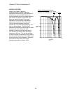
RUN DELAY TIMER
This parameter allows the user to delay the
drive’s recognition of the RUN signal
ROLLBACK GAIN
Note: this function is only for use with multi-
step speed commands (SPD COMMAND SRC
(C1) = MULTI-STEP)
During the start, this function can help the
drive re-establish the torque to help control
rollback (or roll forward).
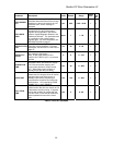
Set-up:
In order to use the Anti-Rollback
function, the following parameters must be set:
SPD REF RELEASE(C1)=BRAKE PICKED
and BRAKE PICK CFRM(C1)=INTERNAL
TIME. With the these settings for SPD REF
RELEASE(C1) and BRAKE PICK CFRM(C1),
the BRAKE PICK TIME (A1) parameter
determines the amount of time the drive will
command zero speed after the Run command
is given and the amount of time the drive will
command zero speed after the Run command
is removed.
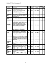
At the start, the ROLLBACK GAIN parameter
will increase the speed regulator gain during
the time determined by BRAKE PICK TIME
parameter when the drive is commanding zero
speed (i.e. the time between the speed
regulator is released and the speed reference
is released). During this BRAKE PICK TIME,
the mechanical brake should be picked (either
by the car controller or drive).
Adjustment:
Start at ROLLBACK GAIN=1 and
increase in increments of 1 to help control
rollback.
IMPORTANT: too high a setting for this
parameter can lead to drive instability.
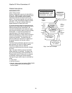
internal connection
READY TO RUN
(logic output)
• software ready
• no faults
• drive boosting
CONTACT
CFIRM
(logic input)
(if used)
RUN or
RUN UP or RUN
DOWN (logic
input)
DRIVE
ENABLE (logic
input)
internal connection
FLUX CONFIRM (logic output)
• flux level 90%
Drive Internal
Signals
Speed
Regulator
and
Reference
Release
Drive Internal Signal
Run Confirm
Run recognition
delay
Speed Deviation High
(
S
p
eed Deviation Alarm
)
S
p
eed Deviation Low
Speed Deviation High
S
p
eed Reference
S
p
eed Feedbac
k
(
S
p
eed Deviation Alarm
)
37