


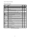
Quattro DC Logic Inputs C2 Submenu
Logic Inputs C2 submenu
(Logic Inputs 1-9)
This parameter defines the function of the logic
inputs.
NOTE: The user can assign particular
functions to each input terminal. Only one
function per terminal is allowed and multiple
terminals cannot have the same function
(except “No Function”). When a function is
assigned to an input terminal, it is removed
from the list of possible selections for
subsequent terminals.
To re-assign a
function to a different terminal one must
first assign “No Function” to the original
terminal so that the desired function is
returned to the list of selections and can be
assigned to a different new terminal.
NOTE: The
current setting of each parameter
is displayed in all caps; all other choices in the
list are displayed in lower case.
Parameter Description Default
Hidden
Item
Run
lock
out
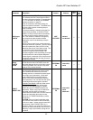
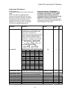
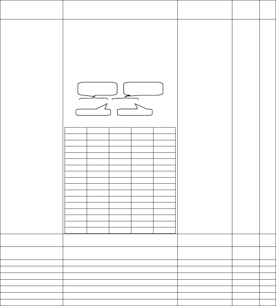
N.C. INPUTS
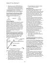
(Normally Closed Inputs) All Logic Inputs may
be configured for use with Normally Open or
Normally Closed external contacts. The
numeric entry is a hexadecimal
representation of a binary control bit for each
channel. A binary 0 means Normally Open.
A binary 1 indicates a Normally Closed
external switch. Logic Input #1 is the least
significant bit. The defaulted value of 0001
indicates logic input 1 is normally closed.
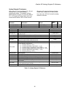
Binary 0000, 0000, 0000, 0000
See table below for converting binary to hex:
Bit 3 Bit 2 Bit 1 Bit 0 Hex
0 0 0 0 0
0 0 0 1 1
0 0 1 0 2
0 0 1 1 3
0 1 0 0 4
0 1 0 1 5
0 1 1 0 6
0 1 1 1 7
1 0 0 0 8
1 0 0 1 9
1 0 1 0 A
1 0 1 1 B
1 1 0 0 C
1 1 0 1 D
1 1 1 0 E
1 1 1 1 F
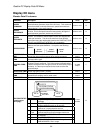
0001 Y Y
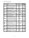
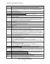
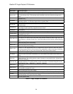
LOGIC INPUT 1 TB1(1)
logic input #1 note: drive comes pre-wired
for logic input #1 to be CONTACT CFIRM
CONTACT CFIRM
Y Y
LOGIC INPUT 2 TB1(2)
logic input #2 note: drive comes pre-wired
for logic input #2 to be CTR PWR SENSE
CTR PWR SENSE Y Y
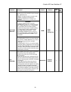
LOGIC INPUT 3 TB1(3)
logic input #3 NO FUNCTION Y Y
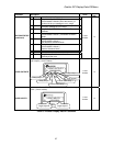
LOGIC INPUT 4 TB1(4)
logic input #4 DRIVE ENABLE Y Y
LOGIC INPUT 5 TB1(5)
logic input #5 RUN Y Y
LOGIC INPUT 6 TB1(6)
logic input #6 UP/DWN Y Y
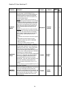
LOGIC INPUT 7 TB1(7)
logic input #7 STEP REF B0 Y Y
LOGIC INPUT 8 TB1(8)
logic input #8 STEP REF B1 Y Y
LOGIC INPUT 9 TB1(9)
logic input #9 FAULT RESET Y Y
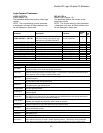
Logic Input #1
Lo
g
ic Input #9
most significant
byte
least significant
byte
61