


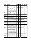
Quattro DC Drive Parameters A1
Adjust A0 menu
Drive A1 submenu
Parameter Description Units Default Range
Hidden
Item
Run
lock
out
fpm 400.0 0.0 – 1500.0
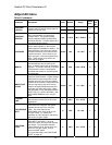
CONTRACT
CAR SPD
(Contract Car Speed)
Adjusts the elevator
contract speed in feet per minute (fpm) or
meters per second (m/s).
m/s 2.000 0.00 – 8.00
N Y
CONTRACT
MTR SPD
(Contract Motor Speed)
Sets motor rpm
when commanded to run at elevator
contract speed. The speed regulator
actually regulates RPM x Encoder PPR
pulses per second. Trim this value to fine
tune actual elevator speed.
rpm 1130.0 30.0 – 3000.0
N Y
RESPONSE
(Response)
Sets the sensitivity of the
drive’s speed regulator in terms of the
speed regulator bandwidth in radians. The
responsiveness of the drive as it follows
the speed reference will increase as this
number increases. If the number is too
large, the motor current and speed will be
jittery. If this number is too small, the
motor will be sluggish.
rad/sec 10.0 1.0 – 20.0
N N
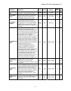
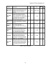
INERTIA
(Per Unit System Inertia) This parameter is
the inertia/torque ratio as seen by the
drive. It affects internal gain of the speed
regulator. This time in seconds is the time
it would take the motor to accelerate a
load-balanced elevator to contract speed
at rated torque.
sec 2.00 0.25 – 50.00
N N
INNER LOOP
XOVER
(Inner Loop Crossover)
This parameter is
used as a stiffness factor. Higher settings
make the drive more responsive to load
changes and can help minimize rollback.
Because of the amount of responsiveness
due to a high setting, the drive is more
sensitive to speed disturbances and this
parameter can affect ride quality. Note:
this parameter is only used when SPEED
REG TYPE (C1) = ELEV SPD REG. See
SPD PHASE MARGIN (A1) if using PI
REG.
rad/sec 2.0 0.1 – 20.0
N N
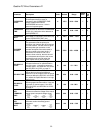
CURRENT
LIMIT
(Armature Current Limit)
This parameter
sets armature current limit for DC motor
applications.
% 200.0 0.0 – 275.0
N N
GAIN REDUCE
MULT
(Gain Reduce Multiplier)
This parameter
is the percent of ‘response’ the speed
regulator should use in the ‘low gain’
mode. This value reduces the
RESPONSE value when the drive is in
‘low gain’ mode. (i.e. setting this
parameter to 100% equals no reduction in
gain in the ‘low gain’ mode)
% 100 10 – 100
Y N
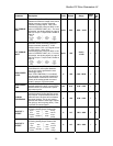
GAIN CHNG
LEVEL
(Gain Change Level)
When the HI/LO
GAIN SRC in submenu C1 is set to
internal, the drive will control the high/low
gain switch. This parameter sets the
speed reference level, above which, the
drive is in ‘low gain’ mode. Units in
percent of rated speed.
For more information, see GAIN CHNG
LEVEL on page 36.
% 100.0 0.0 – 100.0
Y N
30