


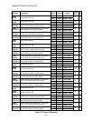
Quattro DC Motor A6 Submenu
48
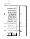
Parameter Description Units Default Range
Hidden
Item
Run
lock
out
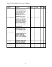
OVLD START LEVEL
(Motor Overload Start Level)
This parameter defines maximum current
at which motor can run continuously
without triggering the motor overload.
One of the two parameters that define the
motor overload curve. Set as a percent
of Rated Motor Current.
% 110 100 – 150
N Y
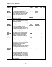
OVLD TIME OUT
(Motor Overload Time Out)
This parameter defines the amount of
time before a motor overload alarm
occurs when the motor is running at the
current level defined below:
⎟
⎟
⎟
⎟
⎟
⎠
⎞
⎜
⎜
⎜
⎜
⎜
⎝
⎛
+
⎟
⎟
⎟
⎠
⎞
⎜
⎜
⎜
⎝
⎛
current
motor
rated
LEVEL
START
OVLD
%40
:
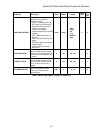
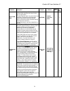
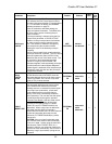
This is the other parameter used to define
the overload curve. For more information
on the motor overload curve, see OVLD
TIME OUT on page 48.
sec 60.0 5.0 – 120.0
N Y
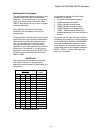
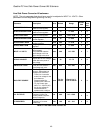
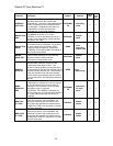
OVLD TIME OUT
This is the other parameter used to define the
overload curve.
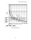
The user can adjust the motor overload
parameters. Three overload curves are shown
in the examples below. Curve #1 is the default
motor overload curve.
OVLD
START
LEVEL
OVLD
TIME
OUT
curve #1 110% 60 sec
curve #2 110% 40 sec
curve #3 120% 70 sec
Motor Overload Parameters
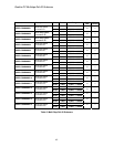
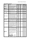
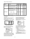
When the motor usage exceeds the user
defined motor overload curve, the drive will
declare a motor overload alarm.
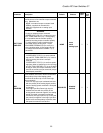
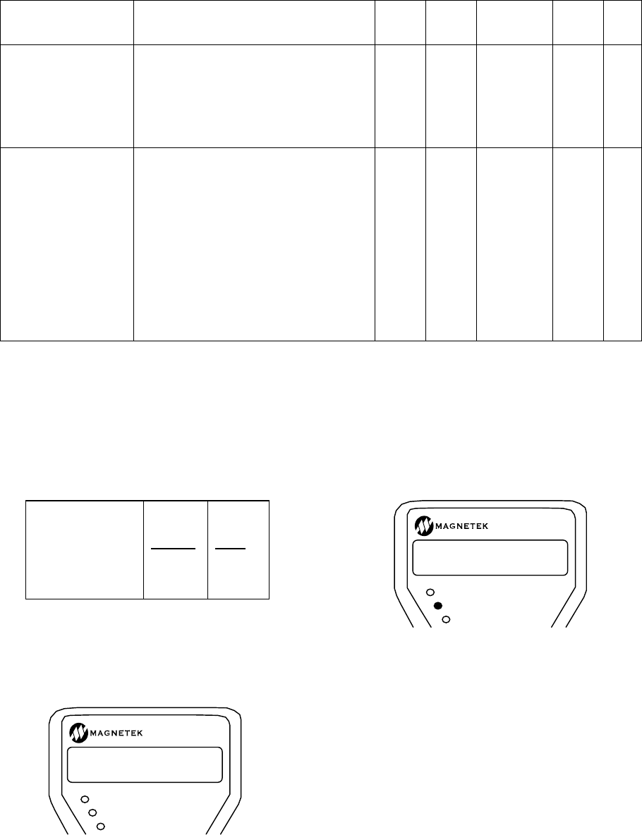
Under the POWER DATA display sub-menu,
the MOTOR OVERLOAD (D2) value displays
the accumulated percent of motor overload trip
level reached. Once this value reaches 100%
the motor overload will trip and a motor
overload alarm is declared by the drive.
The drive will only declare a motor overload
and the user is responsible for taking
appropriate action to protect equipment.
The motor overload alarm can also be
assigned to a logic output. See configuration
sub-menu items, C3.
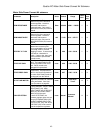
The drive can also be configured so that a
motor overload event declares a Fault, which
will automatically cause the drive to stop. If
this is desirable, the following needs to be
completed:
RUN/FAULT
SUB MENU
DATA ENT
MOTOR OVERLOAD
D2 100%
• logic output configured to MTR
OVERLOAD
• logic input configured to EXT FAULT
• wire the EXT FAULT logic input terminal to
the to MTR OVERLOAD logic output
terminal
• wire the logic input common terminal to the
logic output common
With the above set-up, the drive will then
declare an External Fault on a motor overload.
RUN/FAULT
ALARM!
MTR OVERLOAD
SUB MENU
DATA ENT