


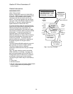
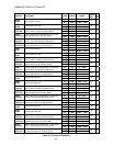
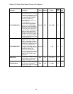
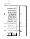

Quattro DC Motor Side Power Convert A4 Submenu
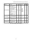
Parameter Description Units Default Range
Hidden
Item
Run
lock
out
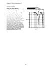
GAIN BANDWIDTH A
(Gain Bandwidth Armature) If
GAIN SELECTION (C1) is set to
MANUAL, this parameter is used
to convert ARM RESISTANCE
(A4) and ARM INDUCTANCE
(A4) into the integral and
proportional gains used by the
current regulator.
If GAIN SELECTION is set to
AUTO-TUNE, this parameter is
used to convert AUTO MEAS
ARM R (D2) and AUTO MEAS
ARM L (D2) into the integral and
proportional gains used by the
current regulator. The higher the
setting, the more faithfully the
regulator will duplicate its input
command, however, too high of a
bandwidth can cause problems
such as a rough ride as the drive
is more responsive.
rad/ sec 500 100 – 2000
N N
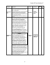
GAIN BANDWIDTH F
(Gain Bandwidth Field) If GAIN
SELECTION is set to AUTO-
TUNE, this parameter is used to
calculate AUTO FLD INT (D2)
and AUTO FLD PROP (D2) into
the integral and proportional
gains used by the field regulator.
The higher the setting, the more
faithfully the regulator will
duplicate its input command,
however, too high of a bandwidth
can cause problems such as a
rough ride as the drive is more
responsive.
rad/ sec 5 1 – 40
N N
PWM FREQ
(PWM Frequency)
This parameter sets the PWM or
‘carrier’ frequency of the motor
armature portion of the drive.
kHz 6.0 2.5 – 16.0
N N
FAN OFF DELAY
(Cooling Fan OFF Delay)
Adjusts OFF delay of all cooling
fans after drive has stopped
operating when Main Fan Control
is set at “Automatic”.
Sec 180 0 – 999
N N
44