


Quattro DC Troubleshooting
Name Description
Possible Causes & Corrective Action
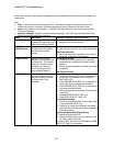
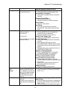
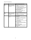
Drive Ovrload
The drive has exceeded the
drive overload curve.
Excessive Field Weakening
Verify Weak Field motor parameter (A5)
Accurate Motor Parameters
Verify motor nameplate values are entered
correctly
Excessive Current Draw
Decrease accel/decel rate
Mechanical brake not releasing properly
Motor Problem
Check for motor failure
Drive Sizing
Verify drive sizing with motor ampere
requirements. May need a larger capacity
drive
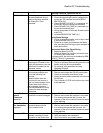
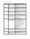
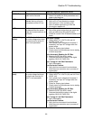
Encoder Flt
The drive is in a run condition
and the encoder is:
not functioning
or
not connected.
or
phasing direction is not proper
with motor rotation
.
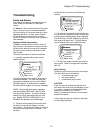
Encoder Phasing Should Match Motor Rotation
If Reversed Tach Fault is indicated the
encoder rotation is backwards
Swap two encoder wires (A and /A)
Encoder Power Supply Loss
Check 12 or 5 volt supply on terminal strip
Accurate Parameters
Verify motor nameplate values are entered
correctly
Verify encoder PPR value is correct
Verify ARMATURE IR DROP (A6) is entered
correctly according to the equation found on
page 47
If problem still occurs, increase the value of
ARMATURE IR DROP (A6)
Response of Speed Regulator
Enter accurate INERTIA (A1) parameter
Increase RESPONSE (A1) parameter
Encoder Coupling Sloppy or Broken
Check encoder to motor coupling
Excessive Noise on Encoder Lines
Check encoder connections. Separate
encoder leads from power wiring (cross power
lead at 90
°)
Ensure that encoder shaft and frame are
electrically isolated from the motor
Hardware Problem
Replace customer Interface PCB.
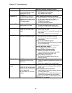
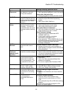
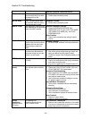
EncoderFault
OFF
(alarm)
When the Encoder Fault is
disabled (ENCODER FAULT
(C1) = disabled), the drive will
display the warning message
“EncoderFault OFF”, every
time the RUN command is
removed.
Check Parameter Settings
Check the setting of parameter ENCODER
FAULT (C1)
Extrn Fault 1
User defined external logic
fault input
...Closure of this contact will
cause the drive to declare the
fault
Check Parameter Settings and External Fault
Signal Wiring
Check the correct logic input is configured for
the correct TB1 terminal and set to EXTRN
FAULT 1 (C2)
Verify the source of the external fault signal.
83