


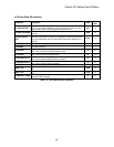
Quattro DC Display Data D0 Menu
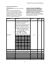
LS Power Data D3 submenu
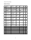
Parameter Description Units
Hidden
Item
LS PWR OUTPUT
(Line Side Power Output) Estimated power transfer to and from the AC
Line. Value is positive when drive is pulling power from the line, and
negative when drive is delivering power back to the line.
kW
N
DC BUS VOLTAGE
(DC Bus Voltage) Measured DC Bus voltage as seen by the line side
controller.
Volts
N
DC BUS VOLTS
REF
(DC Bus Voltage Reference) Calculated applied DC Bus Voltage
reference as the peak of the AC line voltage plus the amount to boost.
For more information, see Line Side Power Convert A5 Submenu on
page 46.
Volts
N
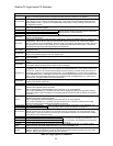
LS OVERLOAD %
(Line Side Overload) N
LS INPUT
CURRENT
(Line Side Input Current) Measured input line current as the average
of the three phases.
Amps
N
LS D AXIS I
(Line Side D Axis Current) Percent of rated current in the D axis.
Note: This is reactive power producing current.
%
N
LS Q AXIS I
(Line Side Q Axis Current) Percent of rated current in the Q axis.
Note: This is power producing current.
%
N
LS D AXIS VOLTS
(Line Side D Axis Voltage) Percent of rated voltage in the Q axis.
Note: This is reactive power producing voltage.
%
N
LS Q AXIS VOLTS
(Line Side Q Axis Voltage) Percent of rated voltage in the Q axis.
Note: This is power-producing voltage.
%
N
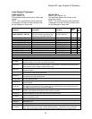
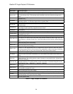
INPUT HZ
(Input Frequency) Measured input line frequency.
Hz
N
INPUT Vab
(Input Voltage A-B Phase) Measured input line-to-line voltage phase
A-B.
Volts
N
INPUT Vca
(Input Voltage C-A Phase) Measured input line-to-line voltage phase
C-A.
Volts
N
LS MODULE TEMP
(Line Side Module Temp) Indicates the hottest of the line side
converters IGBT modules.
°C
N
Table 1 : LS Power Data D2 Submenu 5
69