


Quattro DC Troubleshooting
Name Description
Possible Causes & Corrective Action
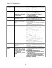
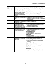
Cont Pwr Lost
Motor contactor power was
removed while the drive was
commanding it to be
energized.
Improper drive On-Run-Stop sequencing
Verify Safety Chain operation
Verify Safety Chain timing
Contactor Flt
The command to close the
contactor and the contactor
feedback do not match for the
time specified by the Contact
Flt Time parameter
Check parameter settings and contactor
Check CONTACT FLT TIME (A1) parameter
for the correct contactor fault time.
Verify wiring to logic input 1 (CONTACT
CFIRM (C2) is correct
Contactor hardware problem
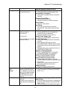
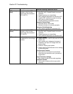
Cube data Flt
The cube data for the motor
side processor is invalid.
Parameters Corrupted
Re-enter parameters and power-cycle
If re-occurs, replace Drive Control board
Cube ID Fault
The cube identification
number for the motor side is
invalid.
Hardware Problem
Power cycle the drive.
Verify the Cube I.D. is properly connected and
fully seated
If re-occurs, replace Drive Control board
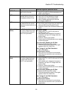
Curr Reg Flt
Measured current does not
match the command current.
Problem with Motor Contactor
Verify that motor contactor is closing
Verify motor contactor is not opening
unexpectedly
Faulty current feedback signals
Verify that reported drive current is zero when
drive is not operating
Verify connections to current transducers
Loss of gate power supply
Verify base block jumper is in place
Incorrect DC Bus Voltage reading
Measure the dc bus with a meter
Compare that with the value on the digital
operator, DC BUS VOLTAGE (D2)
Inaccurate Motor Parameters
Verify motor nameplate values (A6) are
entered correctly
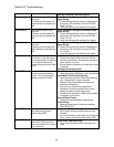
DCU Data Flt
The DCU parameters
checksum is invalid on the
motor side.
Parameters Corrupted
Check & re-enter parameters and power cycle
the drive
If re-occurs, replace Drive Control board
Dir Conflict
(alarm)
Declared when the speed
command is held at zero due
conflict with the analog speed
command polarity and the run
up / run down logic
DIR CONFIRM (C1) must be
enabled.
Check Parameter Settings
Sensitivity determined by the ZERO SPEED
LEVEL (A1)
Confirm Speed Command Polarity
Check polarity of the analog speed command
on analog channel #1
Compare that with the RUN UP (positive) and
RUN DOWN (negative) logic input status
If nuisance, the function can be disabled by DIR
CONFIRM (C1) parameter.
82