


Quattro DC Interconnections
18
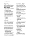
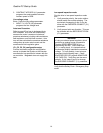
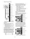
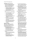
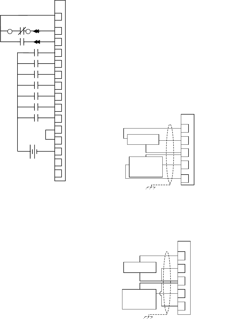
Figure 6: Logic Inputs (External Supply)
Analog Inputs
The Quattro DC has two non-programmable
differential analog input channels.
• Analog input channel 1 is reserved for the
speed command (if used).
• Analog input channel 2 is reserved for the
pre-torque command (if used) or torque
command source (if used).
The analog input channels are bipolar and have
a voltage range of ±10VDC.
Available with the analog channels is multiplier
gain parameters (SPD COMMAND MULT and
EXT TORQUE MULT) and bias parameters
(SPD COMMAND BIAS and EXT TORQUE
BIAS). These parameters are used to scale the
user’s analog command to the proper range for
the drive software. The formula below shows
the scaling effects of these two parameters.
uses
software
drive
signal
MULTBIAS
voltage
input
channel
analog
=×
⎟
⎟
⎟
⎠
⎞
⎜
⎜
⎜
⎝
⎛
−
For more on the multiplier gain or bias
parameters, see Drive A1 submenu on page 30.
The scaling of the analog input signals, with
BIAS set to 0.00 and MULT set to 1.0 follows:
• Speed Command
+10VDC = positive contract speed
-10VDC = negative contract speed
• Pre Torque Command
+10VDC = positive rated pre-torque of motor
-10VDC =
negative rated pre-torque of motor
• Torque Command
+10VDC = positive rated torque of motor
-10VDC =
negative rated torque of motor
NOTE: The drive cannot recognize voltages
outside of the
±10VDC on its analog input
channels.
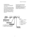
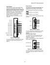
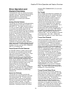
The Quattro DC provides common mode noise
rejection with the differential analog inputs. The
connection of these two differential inputs is
shown in Figure 7.
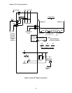
Figure 7: Analog Inputs (Differential)
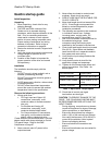
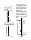
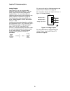
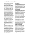
Figure 8 shows the connection for the analog
inputs if they are configured for single-ended
connection. In this configuration, the Quattro
DC noise immunity circuitry is not in effect.
Note: For prevention of ground noise
interference, a twisted shielded pair must be run
to the source and not connected at the board.
PreTorque
Cmd, ±10V
or Torque
Command, ±10V
15
16
18
19
17
analog input 1+
analog input 1-
analog input 2+
analog input 2-
analog input common
TB1
Speed Cmd
±10V
19
PreTorque
Cmd, ±10V
or Torque
Command, ±10V
15
16
18
17
analog input 1+
analog input 1-
analog input 2+
analog input 2-
analog input common
TB1
Speed Cmd
±10V
+24V external
supply
Contact
Cfirm
A
9JCC1-2
A
9JCC1-1
A
9TB1
11
logic input 1
logic input 2
TB1
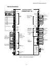
Figure 8: Analog Inputs (Single Ended)
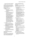
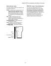
1
2
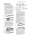
+24VDC isolated
6
5
10
43
46
44
logic input common
C_24VISO
+24VDC isolated
C24VISO
3
4
5
6
7
8
9
logic input 3
logic input 4
logic input 5
logic input 6
logic input 7
logic input 8
logic input 9
45
C24VISO
CTR PWR Sense
+