


Chapter 4 Register-Level Programming
© National Instruments Corporation 4-53 Lab-NB User Manual
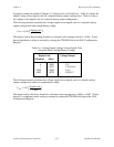
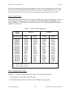
by jumper settings described in Chapter 2, Configuration and Installation. Table 4-5 shows the
output voltage versus digital code for a unipolar analog output configuration. Table 4-6 shows
the voltage versus digital code for a bipolar analog output configuration.
The following formula calculates the voltage output versus digital code for a unipolar analog
output configuration and straight binary coding:
V
out
= 10.0 *
digital code
4,096
The digital code in the preceding formula is a decimal value ranging from 0 to +4,095. Notice
that straight binary coding is selected by clearing the TWOSDA bit in the DAC Configuration
Register.
Table 4-5. Analog Output Voltage Versus Digital Code
(Unipolar Mode, Straight Binary Coding)
Digital Code Voltage Output
(Decimal) (Hex)
0 0000 0 V
1 0001 2.4414 mV
2,048 0800 5.0 V
4,095 0FFF 9.9976 V
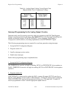
The following formula calculates the voltage output versus digital code for a bipolar analog
output configuration and two's complement coding:
V
out
= 5.0 *
digital code
2,048
The digital code in the above formula is a decimal value ranging from -2,048 to +2,047. Notice
that two’s complement mode coding is selected by setting the TWOSDA bit high in the DAC
Configuration Register.