Chapter 4 Register-Level Programming
© National Instruments Corporation 4-31 Lab-NB User Manual
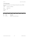
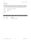
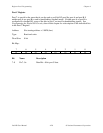
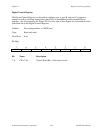
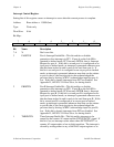
Interrupt Control Register
Setting bits of this register causes an interrupt to occur when the current process is complete.
Address: Base address + 1 0000 (hex)
Type: Write-only
Word Size: 8-bit
Bit Map:
76543210
X X X X PAINTEN PBINTEN TMRINTEN ADCINTEN
Bit Name Description
7–4 X Don’t care bits.
3 PAINTEN Port A Interrupt Enable Bit—This bit enables or disables
generation of an interrupt via PC3. If port A on the Lab-NB is
operated in latched mode, PC3 becomes INTRA, that is, Interrupt
Request for port A. If this bit is set and port A is configured as an
input port in latched mode, an interrupt is generated whenever new
data has been strobed in and is ready to be read from port A. If
this bit is set and port A is configured as an output port in latched
mode, an interrupt is generated whenever new data can be written
to port A; that is, the receiving device has acknowledged the
previous data by driving ACKA* (acknowledge input for port A)
low. If this bit is cleared, interrupts from PC3 are disabled. See
Appendix D, OKI 82C55A Data Sheet, for timing details.
2 PBINTEN Port B Interrupt Enable Bit—This bit enables or disables
generation of an interrupt via PC0. If port B on the Lab-NB is
operated in latched mode, PC0 becomes INTRB, that is, Interrupt
Request for port B. If this bit is set and port B is configured as an
input port in latched mode, an interrupt is generated whenever new
data has been strobed in and is ready to be read from port B. If this
bit is set and port B is configured as an output port in latched
mode, an interrupt is generated whenever new data can be written
to port B; that is, the receiving device has acknowledged the
previous data by driving ACKB* (acknowledge input for port B)
low. If this bit is cleared, interrupts from PC0 are disabled. See
Appendix D, OKI 82C55A Data Sheet, for timing details.
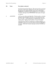
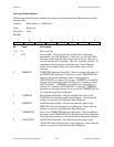
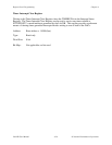
1 TMRINTEN Timer Interrupt Enable Bit—This bit enables interrupts to be
caused by the counter A2 output and the EXTUPDATE* signal. If
this bit is set, an interrupt occurs when either EXTUPDATE* or
counter A2 output makes a low-to-high transition. The interrupt is
cleared by writing either to any of the DAC output registers or to


