


Configuration and Installation Chapter 2
Lab-NB User Manual 2-6 © National Instruments Corporation
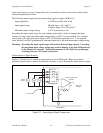
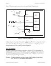
Warning: Connections that exceed any of the maximum ratings of input or output signals on
the Lab-NB may result in damage to the Lab-NB board and to the Macintosh
computer. This includes connecting any power signals to ground and vice versa.
National Instruments is
NOT liable for any damages resulting from any such
signal connections.
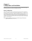
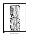
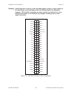
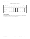
12
34
56
78
9
10
11 12
13 14
15 16
17 18
19 20
21 22
23 24
25 26
27 28
29 30
31 32
33 34
35 36
37 38
39 40
41 42
43 44
45 46
47 48
49 50
ACH1
ACH3
ACH5
DAC0 OUT
DAC1 OUT
ACH7
PA0
PA4
PA6
PB0
PB2
PA2
PB4
PB6
PC0
PC2
PC4
PC6
EXTTRIG
EXTCONV*
GATB0
GATB1
OUTB2
CLKB2
DGND
ACH0
ACH2
ACH4
ACH6
AIGND
AOGND
DGND
PA1
PA3
PA5
PA7
PB1
PB3
PB5
PB7
PC1
PC3
PC5
PC7
EXTUPDATE*
OUTB0
OUTB1
CLKB1
GATB2
+5V
Figure 2-6. Lab-NB I/O Connector Pin Assignments