


Register-Level Programming Chapter 4
Lab-NB User Manual 4-6 © National Instruments Corporation
A/D Configuration Register
The A/D Configuration Register indicates the input channel to be read and the gain for the
analog input circuitry.
Address: Base address + 0 8000 (hex)
Type: Write-only
Word Size: 16-bit
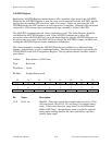
Bit Map:
15 14 13 12 11 10 9 8
X X X X X TBSEL EXTTRIGEN PRETRIG
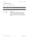
76543210
SCANEN MA2 MA1 MA0 GAIN2 GAIN1 GAIN0 TWOSCMP
Bit Name Description
15–11 X Don’t care bits.
10 TBSEL Clock Select Bit—This bit is used to select the clock source for
A/D conversions. If this bit is cleared, an internal 1-MHz clock
drives the counter (counter A0), and the interval between samples
is the value loaded into counter A0 multiplied by 1 µsec. If this bit
is set, then the output of user-programmable counter B0 is used as
a clock source. The timebase for counter B0 is fixed at 2 MHz and
cannot be changed. The interval between acquired samples is the
value loaded into counter A0 multiplied by the period of the output
signal from counter B0.
9 EXTTRIGEN External Trigger Enable Bit—This bit is one of two bits that
determines the effect of the EXTTRIG signal on the 50-pin I/O
connector. The function of this bit depends on the setting of the
PRETRIG bit. If PRETRIG is set, then this bit has no effect in
either setting. If PRETRIG is cleared and EXTRIGEN is set, then
a rising edge on the EXTTRIG signal starts a sequence of A/D
conversions. Unlike the EXTCONV* line, which controls
individual conversions, EXTTRIG in this case can only start a
multiple A/D conversion DAQ operation with the sample period
determined by the value in counter A0. If both EXTTRIGEN and
PRETRIG are cleared, then the EXTTRIG line on the I/O
connector has no effect.