


Chapter 4 Register-Level Programming
© National Instruments Corporation 4-65 Lab-NB User Manual
Mode 2 Programming Example
Example 1. Configure port A in mode 2:
• Write C0 (hex) to the Digital Control Register.
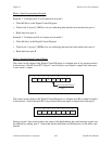
• Wait for bit 7 of port C (OBFA*) to be cleared, indicating that the data last written to port A
has been read.
• Write new data to port A.
• Wait for bit 5 of port C (IBFA) to be set, indicating that data is available in port A to be read.
• Read data from port A.
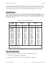
Single Bit Set/Reset Control Words
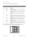
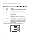
Table 4-8 shows the control words for setting or resetting each bit in port C. Notice that bit 7 of
the control word is cleared for programming the set/reset option for the bits of port C.
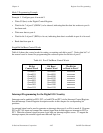
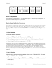
Table 4-8. Port C Set/Reset Control Words
Bit Set
Control Word
Bit Reset
Control Word
The Bit Set
or Reset in Port C
0xxx0001 0xxx0000 xxxxxxxn
0xxx0011 0xxx0010 xxxxxxnx
0xxx0101 0xxx0100 xxxxxnxx
0xxx0111 0xxx0110 xxxxnxxx
0xxx1001 0xxx1000 xxxnxxxx
0xxx1011 0xxx1010 xxnxxxxx
0xxx1101 0xxx1100 xnxxxxxx
0xxx1111 0xxx1110 nxxxxxxx
Interrupt Programming for the Digital I/O Circuitry
Interrupts can be enabled on PC0, PC3, or both PC0 and PC3 via the Interrupt Control Register.
See the Interrupt Control Register description earlier in this chapter for corresponding bit
positions.
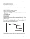
An external signal can be used to generate an interrupt when port A or B is in mode 0. Program
PC0 or PC3 for input and connect the external signal that should trigger an interrupt to PC0 or
PC3. When the external signal becomes logic high, an interrupt request occurs. To negate the
interrupt request, the external signal must become logic low.