


Chapter 5 Calibration
© National Instruments Corporation 5-7 Lab-NB User Manual
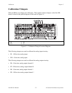
c. Adjust trimpot R9 until the output voltage read is -5 V.
2. Adjust the Analog Output Gain
Adjust the analog output gain by measuring the output voltage generated with the DAC set at
positive full-scale (4,095). This output voltage should be V
+fs
±0.5 LSB. For bipolar output,
V
+fs
= +4.99756 V, and 0.5 LSB = 1.22 mV.
For analog output channel 0:
a. Connect the voltmeter between DAC0 OUT (pin 10 on the I/O connector) and AOGND
(pin 11).
b. Set the analog output channel to +4.99756 V by writing 2,047 to the DAC.
c. Adjust trimpot R6 until the output voltage read is +4.99756 V.
For analog output channel 1:
a. Connect the voltmeter between DAC1 OUT (pin 12 on the I/O connector) and AOGND
(pin 11).
b. Set the analog output channel to +4.99756 V by writing 2,047 to the DAC.
c. Adjust trimpot R8 until the output voltage read is +4.99756 V.
Unipolar Output Calibration Procedure
If your analog output channel is configured for unipolar output, which has an output range of
0 to +10 V, then calibrate your board by completing the following procedure.
1. Adjust the Analog Output Offset
Adjust the analog output offset by measuring the output voltage generated with the DAC set at 0.
This output voltage should be V
-fs
±0.5 LSB. For unipolar output,
V
-fs
= 0 V, and 0.5 LSB = 1.22 mV
For analog output channel 0:
a. Connect the voltmeter between DAC0 OUT (pin 10 on the I/O connector) and AOGND
(pin 11).
b. Set the analog output channel to 0 V by writing 0 to the DAC.
c. Adjust trimpot R7 until the output voltage read is 0 V.