Register-Level Programming Chapter 4
Lab-NB User Manual 4-58 © National Instruments Corporation
This section describes the Digital Control Register, which is used to program the 82C55A ports
in any one of the three modes discussed earlier in this section. Specific control words for each
mode are described later in this section along with programming examples for each mode.
Mode 0 Control Words
Mode 0 provides simple I/O functions for each of the three ports with no handshaking. Each port
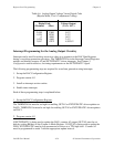
can be assigned as an input port or as an output port. The 16 possible I/O configurations are
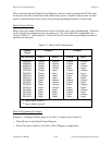
shown in Table 4-7. Notice that bit 7 of the control word is set when programming the mode of
operation for each port.
Table 4-7. Mode 0 I/O Configurations
Control
Word
Group A Group B
Bit 76543210 Port A
Port C
1
Port B
Port C
2
10000000 Output Output Output Output
10000001 Output Output Output Input
10000010 Output Output Input Output
10000011 Output Output Input Input
10001000 Output Input Output Output
10001001 Output Input Output Input
10001010 Output Input Input Output
10001011 Output Input Input Input
10010000 Input Output Output Output
10010001 Input Output Output Input
10010010 Input Output Input Output
10010011 Input Output Input Input
10011000 Input Input Output Output
10011001 Input Input Output Input
10011010 Input Input Input Output
10011011 Input Input Input Input
1
Upper nibble of port C
2
Lower nibble of port C
Mode 0 Programming Examples
Example 1. Configure all three ports (A, B, and C) as output ports in mode 0:
• Write 80 (hex) to the Digital Control Register.
• Write 8-bit data to the Port A, Port B, or Port C Register as appropriate.


