Configuration and Installation Chapter 2
Lab-NB User Manual 2-20 © National Instruments Corporation
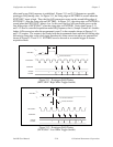
t
ext
Minimum 50 nsec
EXTUPDATE*
DAC OUTPUT
UPDATE
TMRINTUP
DACWRT
t
ext
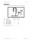
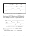
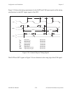
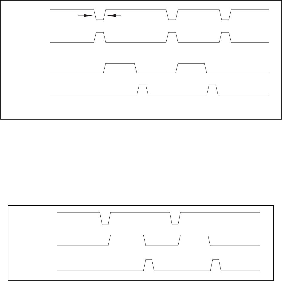
Figure 2-14. Waveform Generation Timing with the EXTUPDATE* Signal
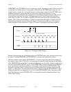
Since a rising edge on the EXTUPDATE* signal always sets the TMRINTUP bit in the Interrupt
Status Register, the EXTUPDATE* signal can also be used for periodic interrupt generation
timed by an external source. The TMRINTUP bit is cleared by writing to either of the two
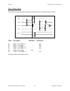
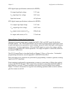
DACs or to the TMRINTCL bit location. Figure 2-15 illustrates a timing sequence where
EXTUPDATE* is being used to generate a NuBus interrupt.
EXTUPDATE*
TMRINTUP
and
NuBusNMR
TMRINTCLR
Figure 2-15. NuBus Interrupt Generation with the EXTUPDATE* Signal
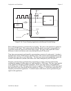
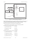
The following specifications and ratings apply to the EXTCONV*, EXTTRIG and
EXTUPDATE* signals.
Absolute maximum voltage input rating -0.5 to 7.0 V with respect to DGND


