


Appendix C Connecting Signals with Accessories
© National Instruments Corporation C-5 653X User Manual
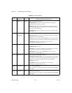
23, 57–58,
25–26,
60–61, 28
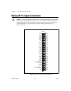
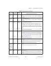
DIOC<0..7> Data Port C bidirectional data lines
Port C is referred to as port number 2 in software. DIOC7 is the MSB; DIOC0
is the LSB.
29, 31–32,
34, 63–64,
66–67
DIOD<0..7> Data Port D bidirectional data lines
Port D is referred to as port number 3 in software. DIOD7 is the MSB; DIOD0
is the LSB.
40 CPULL Bias
Selection
Control pull-up/pull-down selection
Input signal that selects whether the 653X device pulls the timing and
handshaking control lines (REQ, ACK, PCLK, and STOPTRIG) up or down
when undriven. If you connect CPULL to +5 V on the external terminal
connector, the 653X device pulls the control lines up. If you connect CPULL
to GND or leave CPULL unconnected, the 653X device pulls the control lines
down.
See power on state the Power-On State section in Appendix D, Hardware
Considerations, for more information.
38 DPULL Bias
Selection
Data pull-up/pull-down selection
Input signal that selects whether the 653X device pulls the data lines (DIOA,
DIOB, DIOC, and DIOD) up or down when undriven. If you connect DPULL
to +5 V on the external terminal connector, the 653X device pulls the data lines
up. If you connect DPULL to GND or leave DPULL unconnected, the 653X
device pulls the data lines down.
See power on state the Power-On State section in Appendix D, Hardware
Considerations, for more information.
1 +5 V Power 5V output
Line that provides a maximum of 1 A of power. This line is protected by an
onboard fuse that shuts off power when there is too much current and
automatically resets itself after current returns to normal.
11, 14, 18,
20, 24, 27,
30, 36–37,
39, 41–42,
46, 49–50,
55, 59, 62,
65, 68
GND Power Ground
These lines are the ground reference for all other signals.
19, 35, 43,
56
RGND Power Reserved ground
These lines offer additional ground pins. If you are using an R6868 ribbon
cable for example, these lines can be used as additional ground references. If
you are using an SH68-68-D1, however, these signals are not connected.
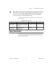
Table C-3.
Signal Descriptions (Continued)
Pins Signal Name
Signal
Type
Signal Description Based on Mode Used