


Chapter 2 Using Your 653X
© National Instruments Corporation 2-27 653X User Manual
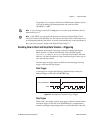
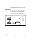
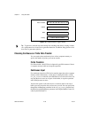
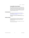
Deciding Which Lines You Want to Monitor
You need to specify which of the lines in your acquisition you want to
monitor for changes.
Specify which bits are significant to you by using a software line mask in
the
DIG_Trigger_Config
function in NI-DAQ C interface, and the
Digital Trigger Config VI for LabVIEW. In the following example, the user
specifies the mask to detect changes on the two least-significant bits of a
port. Pattern 1 does not have changes in the two bits of interest and data is
not latched, but for pattern 2, a change is detected on one of the two bits of
interest, and the value of the entire port is acquired.
Figure 2-15.
Change Detection Example Settings
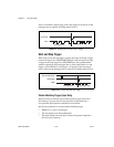
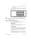
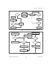
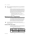
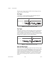
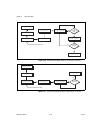
Deciding How to Start and Stop Data Transfer—Triggering
By default, data transfer starts upon a software command (the
Digital Buffer Control VI called by the DIO Start VI in LabVIEW and the
DIG_Block_In
and
DIG_Block_Out
functions in NI-DAQ C interface).
However, you have the option of using a hardware trigger to start, stop, or
start and stop data transfer.
16 bits Port 0, Port 1 Group 1
Port 2, Port 3 Group 2
32 bits Port 0, Port 1, Port 2, Port 3 Group 1
Mask 00000011
Initial Input
Pattern
00000010
Input Pattern 1 01000010
No change on specified
bits.
Data is not latched.
Input Pattern 2 00000011
Change detected,
latch entire port.
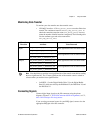
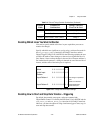
Table 2-4.
Port and Timing Controller Combinations (Continued)
Transfer
Width
Possible Port
Combinations
Timing Controllers
That Can Be Used