


Chapter 3 Timing Diagrams
© National Instruments Corporation 3-3 653X User Manual
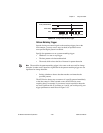
during, or after the REQ edge. If STARTRIG is asserted too close to the REQ edge, it may
not be recognized until the next REQ edge. To avoid this uncertainty, you can observe an
optional setup time of 15 ns, in other words, assert STARTRIG at least 15 ns before the
start of the REQ pulse.
The STARTRIG signal is synchronized to the REQ edge using a flip-flop.
Because of this synchronization flip-flop, there is a one REQ-pulse delay
after STARTRIG before the data capture begins. There is a possibility of a
two-cycle delay if you do not observe the optional setup time mentioned in
the previous note.
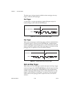
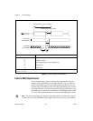
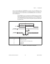
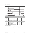
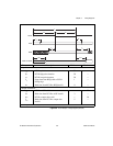
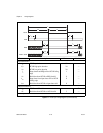
Figure 3-2.
External Request Timing Diagram
Parameter Description
t
c
Cycle time
t
hw
Width of low pulse
t
p
Propagation time to valid output data
t
su
Setup time
t
h
Hold time
Data Valid
(Output Mode)
Data Valid
(Input Mode)
REQ
t
h
t
su
10 ns
Min
20 ns
Min
t
p
30 ns Max
t
hw
20 ns Min
20 ns Min
t
c
50 ns Min
t
w