


Appendix D Hardware Considerations
© National Instruments Corporation D-11 653X User Manual
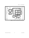
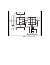
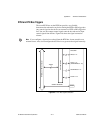
RTSI and PXI Bus Triggers
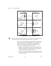
The seven RTSI lines on the RTSI bus provide a very flexible
interconnection scheme for any device sharing the RTSI or PXI-trigger bus.
Any control signal on the device can connect to a RTSI or PXI-trigger bus
line. You can drive output control signals onto the bus and receive input
control signals from the bus. Figure D-6 shows the signal connection
scheme.
Note
If you configure a signal to be received from the RTSI bus, do not attach it to an
external source. Also, do not configure the 653X device to generate that signal internally.
Figure D-6.
RTSI Bus Signal Connection
RTSI Bus or PXI Connector
Crossbar Switch
Trigger
20 MHz Timebase
REQ<1..2>
ACK<1..2>
(STARTTRIG<1..2>)
PCLK<1..2>
DAQ-DIO
STOPTRIG<1..2>
Switch
7
2
2
2
2