


Appendix D Hardware Considerations
653X User Manual D-10 ni.com
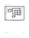
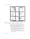
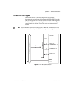
RTSI and PXI Trigger Bus Interfaces
You can use the seven bidirectional RTSI lines on the RTSI bus to share
signals between devices. Use the RTSI bus interface to synchronize
multiple cards or change control signals with multiple devices.
The PCI-6534, PCI-DIO-32HS and AT-DIO-32HS each contain a RTSI
connector and an interface to the National Instruments RTSI bus. The RTSI
bus provides seven trigger lines and a system clock line. All National
Instruments AT- and PCI-bus devices that have RTSI bus connectors can be
cabled together inside a computer to share these signals.
The PXI-653X uses pins on the PXI J2 connector to connect the RTSI bus
to the PXI trigger bus as defined in the PXI Specification, rev. 1.0. All
National Instruments PXI modules that provide a connection to these pins
can be connected together by software. This feature is available only when
the PXI-653X is used in a PXI-compatible chassis. It is not supported in
CompactPCI chassis.
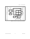
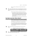
Board, RTSI, and PXI Bus Clocks
The 653X device requires a clock to run the handshaking logic and to
generate sampling intervals for pattern I/O. The frequency timebase must
be 20 MHz.
The 653X device can use its internal 20 MHz clock source, or you can
provide a clock from another 20 MHz device over the RTSI bus. When
using its internal 20 MHz clock, the 653X device can also drive its internal
timebase onto the bus and to another device that uses a 20 MHz clock.
Whether internal or external, the 20 MHz clock serves as the primary
frequency source for the 653X device. By default, the 653X device uses an
internal clock. You can programmatically change the source of the clock
through software.
♦ PXI-6533—The PXI-6533 uses PXI trigger line 7 as the RTSI clock line.