


Chapter 2 Using Your 653X
© National Instruments Corporation 2-31 653X User Manual
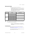
Choosing DMA or Interrupt Transfers
When using DMA (by default), the 6534 device transfers data in 32-byte
blocks and the 6533 device transfers data in 4 byte blocks. Therefore, at any
time during a continuous operation, there may be up to 31 bytes (or 3 bytes
for 6533 devices) of data in an internal device FIFO. You can use interrupt
driven transfers if you need to retrieve data immediately as it is acquired.
Interrupt driven transfers are slower and take more processing time from
the computer than DMA driven transfers.
Connecting Signals
Connect digital input signals to the I/O connector using the pinout
diagrams, Figures C-1, 653X I/O Connector 68-Pin Assignments, or C-2,
68-to-50-Pin Adapter Pin Assignments.
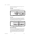
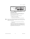
If you are using external start and/or stop triggers, connect to the
appropriate pins—start trigger (ACK or STARTTRIG) and/or stop trigger
(STOPTRIG).
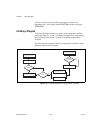
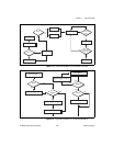
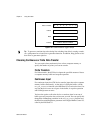
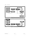
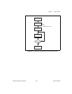
Creating a Program
Using the following flowcharts as a guide, create a program to perform
change detection. Figure 2-21 and 2-22 display flowcharts for C
programming using NI-DAQ, while Figure 2-22 shows a LabVIEW
programming flowchart.
The boxes represent function names for the appropriate software, and the
diamonds represent decision points.