


Chapter 3 Timing Diagrams
653X User Manual 3-26 ni.com
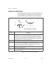
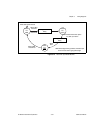
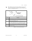
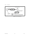
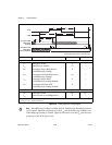
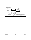
Figure 3-22. Trailing Edge Input Timing Diagram
Note
When REQ-edge latching is enabled (default), the REQ edge determines when data
will be latched. Input data valid needs to be held t
r*di
after the trailing edge of REQ occurs.
When REQ-edge latching is disabled, input data valid needs to be held t
adi
after the active
going edge of the ACK signal occurs.
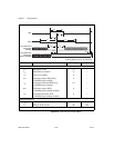
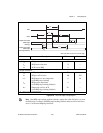
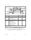
Parameter Description Minimum Maximum
Input Parameters
t
rr*
REQ pulse width 75 —
t
r*r
REQ inactive duration 75 —
t
dir*
Input data setup to REQ inactive
(with REQ-edge latching)
0 —
t
r*di
Input data hold from REQ inactive
(with REQ-edge latching)
10 —
t
dir
Input data setup to REQ
(with REQ-edge latching disabled)
0 —
t
adi
Input data hold from ACK
(with REQ-edge latching disabled)
0 —
Output Parameters
t
aa*
ACK pulse width 225
1
275
2
t
a*r*
ACK inactive to next REQ inactive 0 —
1
t
aa*
(min.)
= 225 + programmable delay
2
t
aa*
(max) = 275 + programmable delay
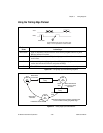
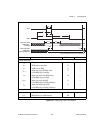
REQ
Input Data Valid
(REQ-edge
latching)
Input Data Valid
(REQ-edge
latching disabled)
t
dir*
t
r*r
t
dir
t
aa*
t
a*r*
t
rr*
t
r*di
ACK
t
adi
ACK and REQ are shown as active high