


Chapter 3 Timing Diagrams
653X User Manual 3-2 ni.com
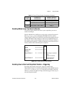
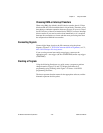
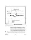
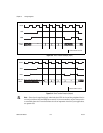
Figure 3-1. Internal Request Timing Diagram
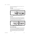
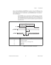
External REQ Signal Source
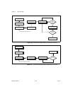
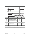
Use an external request when you want to time data transfers using an
external signal on the REQ pin of the I/O connector. You can select the
polarity of the REQ signal. If active high (default), the 653X device will
latch the data on the I/O pins on the rising edge of the REQ signal. If active
low, the 653X device will latch the data on the I/O pins on the falling edge
of the REQsignal. The low timeand high time ofthe REQsignal must each
be >20 ns. The minimum duration for a period of the REQ signal is 50 ns.
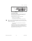
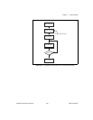
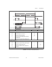
Note
For data transfers that use a hardware start trigger, there is no mandatory setup (t
su
)
or hold time (t
h
) for the STARTRIG (ACK) signal. It can be asserted at any point before,
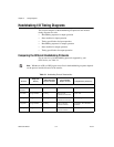
Parameter Description
t
c
*
Cycle time
t
w
*
Width of pulse
t
p
Propagation time to valid output data
t
su
Setup time
t
h
Hold time
* The 6534 devices will transfer data at 20 MHz when the cycle time (t
c
) for REQ pulse is 50 ns and width of the REQ
pulse (t
w
) is 20–30 ns.
dtp will remove bar
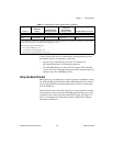
Data Valid
(Output Mode)
Data Valid
(Input Mode)
t
su
30 ns
Min
t
h
0ns
Min
t
p
30 ns
Max
t
c
Programmable = Interval x Timebase
Programmable = One Timebase
REQ if Active High
REQ if Active Low
t
w