


© National Instruments Corporation C-1 653X User Manual
C
Connecting Signals with
Accessories
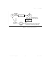
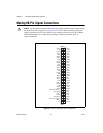
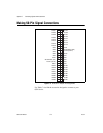
This appendix describes how to connect signals to your 653X device. Use
the first part of the appendix to acquaint yourself with the device control
signals. Then go to appropriate pinout diagrams (68 or 50-pin), which
display the layout of pin locations.
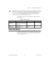
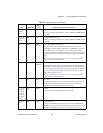
Control Signals
Use the four control signals to regulate/control the timing of your data
transfer when using the handshaking and pattern I/O modes. The direction
and function of each signal varies, depending on the mode of operation,
as shown in Table C-1.
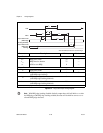
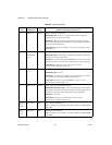
Table C-1.
Control Signals for Handshaking I/O and Pattern I/O
Signal Name
Handshaking I/O Pattern I/O
Direction Function Direction Function
REQ<1..2> Input Request—Indicates
that the peripheral
device is ready
Input or
Output
Request—
Clocks the data transfer
ACK<1..2>
or
STARTTRIG<1..2>
Output Acknowledge—
Indicates the 653X
device is ready
Input Start trigger
STOPTRIG<1..2> N/A N/A Input Stop trigger
PCLK<1..2> Input or
Output
Peripheral clock N/A N/A