


Appendix D Hardware Considerations
© National Instruments Corporation D-9 653X User Manual
There is no specific cutoff frequency at which termination becomes
necessary.
Note
A purely resistive termination scheme is not recommended because of the current
drawn by the termination resistors. For example, a 90 Ω terminating resistor works well to
dampen reflections, but sinks 27 mA even at 2.4 V. The DIO-32HS is only rated to sink
24 mA.
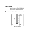
Follow these signal-conditioning recommendations for optimum use:
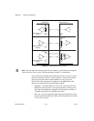
• Separate 653X device signal lines from high-current or high-voltage
lines. These lines are capable of inducing currents in or voltages on the
653X device signal lines if they run in parallel paths at a close distance.
To reduce the magnetic coupling between lines, separate them by a
reasonable distance if they run in parallel, or run the lines at right
angles to each other.
• Do not run signal lines through conduits that also contain power lines.
How Much Current Can I Sink or Source?
Make sure the sink current does not exceed 24 mA at 0.4 V to guarantee
that TTL low voltage specifications are met. The sink current is the amount
of current that flows into the 653X device when it asserts a TTL low signal
(often denoted by I
out
or I
ol
under Output Low Voltage specification).
Also, it is important to make sure the source current does not exceed
–24 mA at 2.4 V to guarantee TTL high voltage specifications. The source
current is the amount of current that flows out of the 653X device when it
asserts a TTL high signal (often denoted by I
out
or I
oh
under output high
voltage specification).
Note
Most National Instruments digital I/O products have similar source and sink
currents.
Note
If you are using the DAQCard-6533 for PCMCIA, your PCMCIA socket may not
provide sufficient power to drive all outputs at 24 mA.
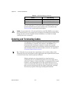
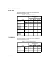
Table D-2.
Sink and Source Current for the 653X Devices
Sink Current Source Current
24 mA at 0.4 V –24 mA at 2.4 V