


Chapter 2 Using Your 653X
© National Instruments Corporation 2-19 653X User Manual
For example, if you specify a timebase of 100 kHz and a timebase divisor
of 25, the resulting acquisition/generation rate would be 4 kHz.
100 kHz/25 = 4 kHz.
Note
If you are using a version of NI-DAQ prior to version 6.8, the minimum value for
timebase divisor is 2.
Note
In LabVIEW, you can specify the transfer rate directly using the Digital Clock
Config VI (called by the DIO Start VI). The software will choose the closest transfer rate
by selecting the frequency and divisor. To see the actual transfer rate, create an indicator at
the actual clock frequency output of the Digital Clock Config VI.
Deciding How to Start and Stop Data Transfer—Triggering
By default, data transfer starts upon a software command (the Digital
Buffer Control VI called by the DIO Start VI in LabVIEW and the
DIG_Block_In
and
DIG_Block_Out
functions in NI-DAQ C interface).
However, you have the option of using a hardware trigger to start, stop, or
start and stop data transfer.
The three types of trigger signals available are the start trigger, the stop
trigger, or the start and stop trigger.
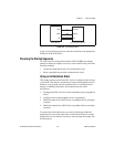
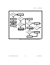
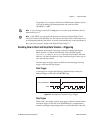
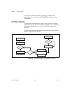
Start Trigger
A start trigger is a trigger that initiates a pattern I/O upon receipt of a
hardware trigger on the ACK (STARTTRIG) pin.
Figure 2-8.
Starting Data Transfer Using a Trigger
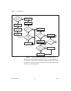
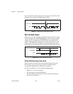
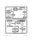
Stop Trigger
When using a stop trigger, transfer starts upon a software command. Once
a hardware trigger is received on the STOPTRIG pin, a predetermined
amount of pretrigger and posttrigger data is saved in the buffer. Once this
REQ
ACK (STARTTRIG)
Posttrigger Data