


Chapter 2 Using Your 653X
© National Instruments Corporation 2-23 653X User Manual
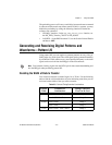
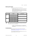
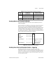
Monitoring Data Transfer
To monitor your data transfer once data transfer starts:
• NI-DAQ C interface—Call
DIG_Block_Check
to monitor finite data
transfer. For continuous transfers, use
Get_DAQ_Device_Info
to
obtain the cumulative transfer count (
DIG_Block_Check
does not
return the number of buffer iterations completed). The following table
lists the attribute types and values returned for
Get_DAQ_Device_Info
:
Note
You should always read the least significant bits of the transfer count before reading
the most significant bits. The 32 most significant bits of the transfer count is cached in
software when you read the least significant bits.
• LabVIEW—Use the Digital Buffer Write VI or the Digital Buffer
Read VI, which are called by the DIO Read VI, the DIO Write VI, and
the DIO Wait VI.
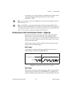
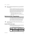
Connecting Signals
Connect digital input signals to the I/O connector using the pinout
diagrams, Figures C-1, 653X I/O Connector 68-Pin Assignments, or C-2,
68-to-50-Pin Adapter Pin Assignments.
If you are using an external source for your REQ signal, connect it to the
appropriate REQ pin of the I/O connector.
Transfer
Direction
Attribute Value Returned
Input
ND_READ_MARK_H_SNAPSHOT_GR1
Most significant 32-bit of transfer count
ND_READ_MARK_H_SNAPSHOT_GR1
ND_READ_MARK_L_SNAPSHOT_GR1
Least significant 32-bit of transfer count
ND_READ_MARK_L_SNAPSHOT_GR2
Output
ND_WRITE_MARK_H_SNAPSHOT_GR1
Most significant 32-bit of transfer count
ND_WRITE_MARK_H_SNAPSHOT_GR2
ND_WRITE_MARK_L_SNAPSHOT_GR1
Least significant 32-bit of transfer count
ND_WRITE_MARK_L_SNAPSHOT_GR2