


Chapter 2 Using Your 653X
653X User Manual 2-4 ni.com
Connecting Signals
Connect digital input signals to the I/O connector using the pinout
diagrams, Figures C-1, 653X I/O Connector 68-Pin Assignments,
and C-2, 68-to-50-Pin Adapter Pin Assignments.
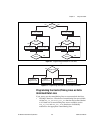
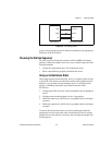
Creating a Program
Using the following flowcharts as a guide, create a program to perform
unstrobed I/O. Figure 2-1 displays a flowchart for C programming using
NI-DAQ, while Figure 2-2 shows a LabVIEW programming flowchart.
The boxes represent function names for the appropriate software, and the
diamonds represent decision points.
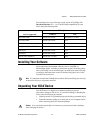
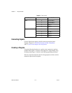
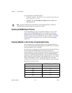
Table 2-1.
Port 4 Lines
Direction Line I/O Pins
Input 0 STOPTRIG 1
1 STOPTRIG 2
2 REQ 1
3 REQ 2
Output (standard) 0 PCLK 1
1 PCLK 2
2 ACK 1
3 ACK 2