


Chapter 3 Hardware Overview
PCI-6110E/6111E User Manual 3-2
©
National Instruments Corporation
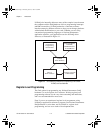
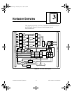
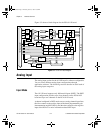
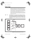
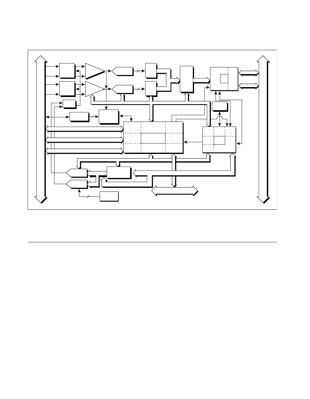
Figure 3-2 shows a block diagram for the PCI-6111E board.
Figure 3-2. PCI-6111E Block Diagram
Analog Input
The analog input section for the 611
X
E
board is software configurable.
You can select different analog input configurations through
application software. The following sections describe in detail each of
the analog input categories.
Input Mode
The 611
X
E board supports only differential inputs (DIFF). The DIFF
input configuration provides up to four channels on the PCI-6110E
board and up to two channels on the PCI-6111E board.
A channel configured in DIFF mode uses two analog channel input lines.
One line connects to the positive input of the board programmable gain
instrumentation amplifier (PGIA), and the other connects to the negative
input of the PGIA. For more information about DIFF input
Timing
PFI / Trigger
I/O Connector
RTSI Bus
PCI Bus
Digital I/O (8)
EEPROM
+
CH0
Amplifier
–
Calibration
Mux
AI CH0
Mux
CH0
Latch
Analog
Trigger
Circuitry
2
Trigger Level
DACs
Trigger
12
4
Calibration
DACs
DAC0
DAC1
CH0
12-Bit ADC
DAQ - STC
Analog Input
Timing/Control
Analog Output
Timing/Control
Digital I/O
Trigger
Counter/
Timing I/O
RTSI Bus
Interface
DMA/IRQ
Bus
Interface
DAC
FIFO
Data (32)
Address/Data
Control
Data (32)
Analog
Input
Control
EEPROM
Control
DMA
Interface
FPGA
DAQ-STC
Bus
Interface
Analog
Output
Control
I/O
Bus
Interface
Mini
MITE
Generic
Bus
Interface
PCI
Bus
Interface
IRQ
DMA
AO Control
CH0+
CH0-
+
CH1
Amplifier
–
AI CH1
Mux
CH1
Latch
12
CH1
12-Bit ADC
CH1+
CH1-
AI Control
Data (16)
Data (16)
ADC
FIFO
PCI_E.book Page 2 Thursday, June 25, 1998 12:55 PM