


Chapter 4 Signal Connections
PCI-6110E/6111E User Manual 4-14
©
National Instruments Corporation
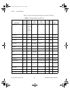
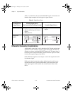
Caution: Exceeding the maximum input voltage ratings, which are listed in
Table 4-2, can damage the 611X E board and the computer. National
Instruments is
NOT
liable for any damages resulting from such signal
connections.
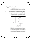
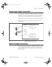
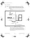
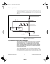
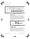
Figure 4-6 shows signal connections for three typical digital I/O
applications.
Figure 4-6. Digital I/O Connections
Figure 4-6 shows DIO<0..3> configured for digital input and
DIO<4..7> configured for digital output. Digital input applications
include receiving TTL signals and sensing external device states such
as the switch state shown in Figure 4-6. Digital output applications
include sending TTL signals and driving external devices such as the
LED shown in Figure 4-6.
!
LED
+5 V
TTL Signal
+5 V
DIO<4..7>
DIO<0..3>
DGND
Switch
I/O Connector
611
X
E Board
PCI_E.book Page 14 Thursday, June 25, 1998 12:55 PM