


Chapter 4 Signal Connections
PCI-6110E/6111E User Manual 4-24
©
National Instruments Corporation
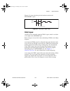
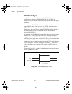
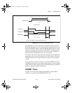
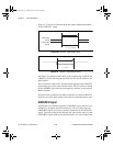
Refer to Figures 4-8 and 4-9 for the relationship of STARTSCAN to the
DAQ sequence.
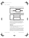
As an input, the CONVERT* signal is configured in the edge-detection
mode. You can select any PFI pin as the source for CONVERT* and
configure the polarity selection for either rising or falling edge. The
selected edge of the CONVERT* signal initiates an A/D conversion.
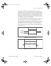
As an output, the CONVERT* signal reflects the actual convert pulse
that is connected to the ADC. This is true even if the conversions are
being externally generated by another PFI. The output is an active low
pulse with a pulse width of 50 to 100 ns. This output is set to tri-state at
startup.
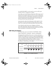
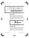
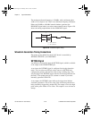
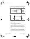
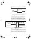
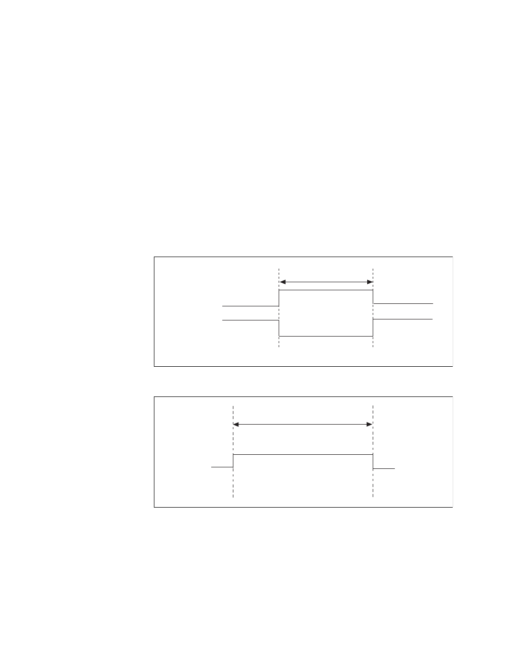
Figures 4-18 and 4-19 show the input and output timing requirements
for the CONVERT* signal.
Figure 4-18. CONVERT* Input Signal Timing
Figure 4-19. CONVERT* Output Signal Timing
The ADC switches to hold mode within 20 ns of the selected edge. This
hold-mode delay time is a function of temperature and does not vary
from one conversion to the next.
Rising-edge
polarity
Falling-edge
polarity
t
w
t
w
= 10 ns minimum
t
w
t
w
= 50-100 ns
PCI_E.book Page 24 Thursday, June 25, 1998 12:55 PM