Chapter 3 Hardware Overview
PCI-6110E/6111E User Manual 3-6
©
National Instruments Corporation
Analog Trigger
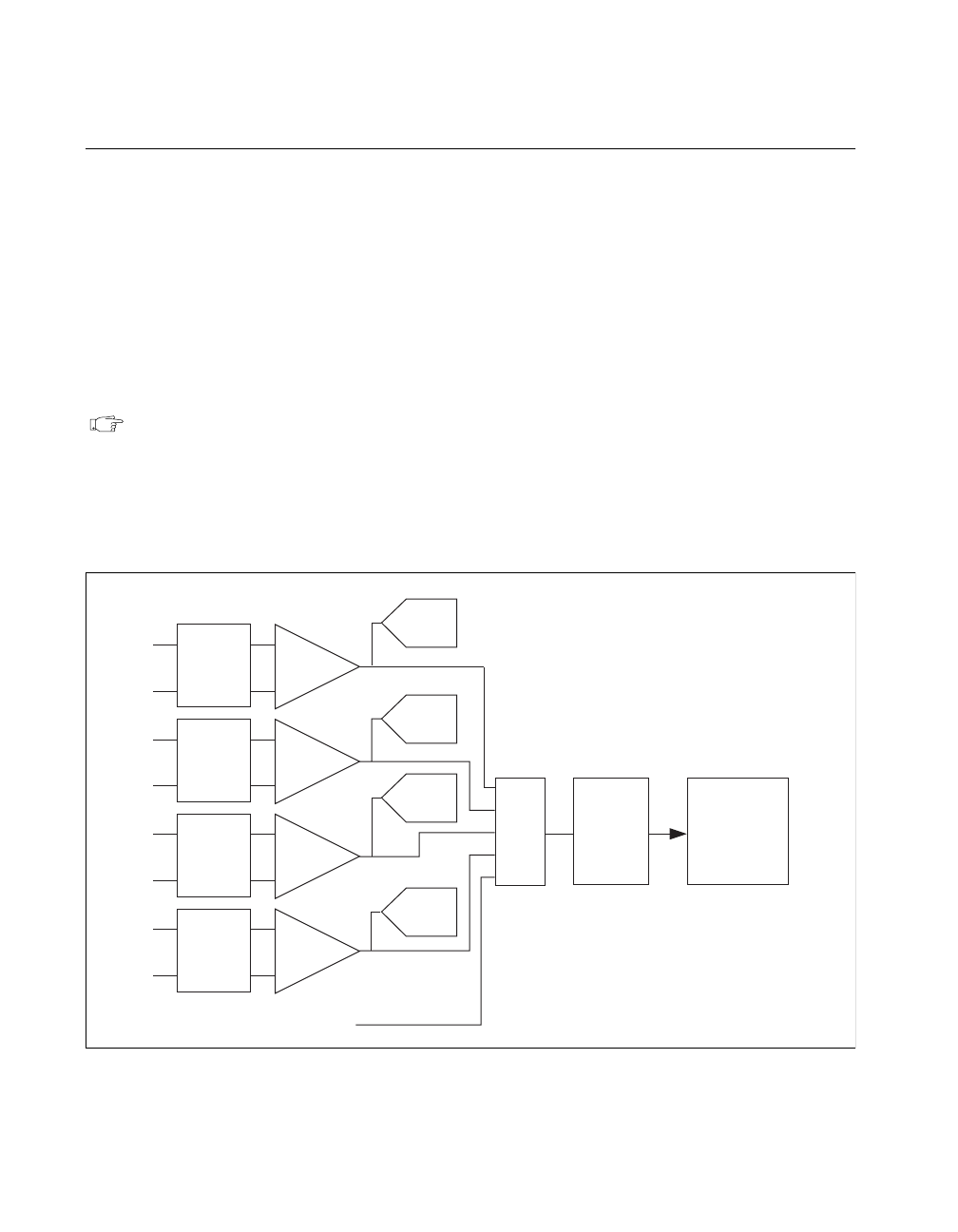
In addition to supporting internal software triggering and external
digital triggering to initiate a data acquisition sequence, these boards
also support analog triggering. You can configure the analog trigger
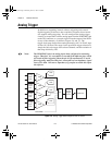
circuitry to accept either a direct analog input from the PFI0/TRIG1 pin
on the I/O connector or a postgain signal from the output of the PGIA
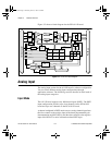
on any of the channels, as shown in Figures 3-4 and 3-5. The
trigger-level range for the direct analog channel is ±10 V in 78 mV steps
for the 611
X
E
board. The range for the post-PGIA trigger selection is
simply the full-scale range of the selected channel, and the resolution is
that range divided by 256.
Note: The PFI0/TRIG1 pin is an analog input when configured as an analog
trigger. Therefore, it is susceptible to crosstalk from adjacent pins, which
can result in false triggering when the pin is left unconnected. To avoid
false triggering, make sure this pin is connected to a low-impedance signal
source (less than 1 kΩ source impedance) if you plan to enable this input
via software.
Figure 3-4.
Analog Trigger Block Diagram for the PCI-6110E
PGIA
Analog
Input
CH0
+
-
ADC
ADC
ADC
DAQ-STC
Analog
Trigger
Circuit
Mux
PGIA
Analog
Input
CH1
+
-
PGIA
Analog
Input
CH2
+
-
PGIA
Analog
Input
CH3
+
-
ADC
PFI0/TRIG1
PCI_E.book Page 6 Thursday, June 25, 1998 12:55 PM


