


Chapter 4 Signal Connections
©
National Instruments Corporation 4-5 PCI-6110E/6111E User Manual
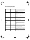
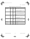
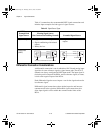
PFI6/WFTRIG DGND Input
Output
PFI6/Waveform Trigger—As an input, this is one of the
PFIs.
As an output, this is the WFTRIG signal. In timed analog
output sequences, a low-to-high transition indicates the
initiation of the waveform generation.
PFI7/STARTSCAN DGND Input
Output
PFI7/Start of Scan—As an input, this is one of the PFIs.
As an output, this is the STARTSCAN signal. This pin
pulses once at the start of each analog input scan in the
interval scan. A low-to-high transition indicates the start of
the scan.
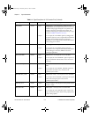
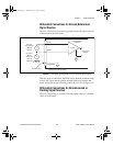
PFI8/GPCTR0_SOURCE DGND Input
Output
PFI8/Counter 0 Source—As an input, this is one of the
PFIs.
As an output, this is the GPCTR0_SOURCE signal. This
signal reflects the actual source connected to the
general-purpose counter 0.
PFI9/GPCTR0_GATE DGND Input
Output
PFI9/Counter 0 Gate—As an input, this is one of the PFIs.
As an output, this is the GPCTR0_GATE signal. This signal
reflects the actual gate signal connected to the
general-purpose counter 0.
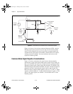
GPCTR0_OUT DGND Output Counter 0 Output—This output is from the general-purpose
counter 0 output.
FREQ_OUT DGND Output Frequency Output—This output is from the frequency
generator output.
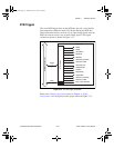
Table 4-1. Signal Descriptions for I/O Connector Pins (Continued)
Signal Name Reference Direction Description
PCI_E.book Page 5 Thursday, June 25, 1998 12:55 PM