


Chapter 3 Hardware Overview
©
National Instruments Corporation 3-7 PCI-6110E/6111E User Manual
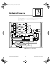
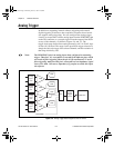
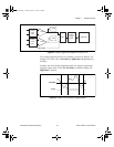
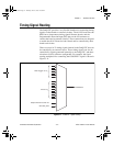
Figure 3-5. Analog Trigger Block Diagram for the PCI-6111E
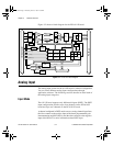
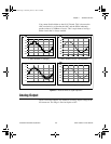
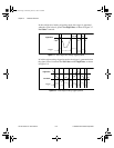
Five analog triggering modes are available, as shown in Figures 3-6
through 3-10. You can set lowValue and highValue independently in
software.
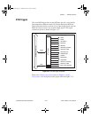
In below-low-level analog triggering mode, the trigger is generated
when the signal value is less than lowValue, as shown in Figure 3-6.
HighValue is unused.
Figure 3-6. Below-Low-Level Analog Triggering Mode
PGIA
Analog
Input
CH0
+
-
ADC
DAQ-STC
Analog
Trigger
Circuit
Mux
PGIA
Analog
Input
CH1
+
-
ADC
PFI0/TRIG1
lowValue
Trigger
PCI_E.book Page 7 Thursday, June 25, 1998 12:55 PM