


Chapter 4 Signal Connections
©
National Instruments Corporation 4-33 PCI-6110E/6111E User Manual
actions as starting and stopping the counter, generating interrupts,
saving the counter contents, and so on.
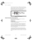
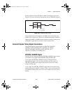
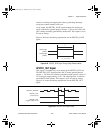
As an output, the GPCTR1_GATE signal monitors the actual gate
signal connected to general-purpose counter 1. This is true even if the
gate is being externally generated by another PFI. This output is set to
tri-state at startup.
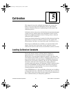
Figure 4-30 shows the timing requirements for the GPCTR1_GATE
signal.
Figure 4-30. GPCTR1_GATE Signal Timing in Edge-Detection Mode
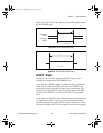
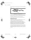
GPCTR1_OUT Signal
This signal is available only as an output on the GPCTR1_OUT pin.
The GPCTR1_OUT signal monitors the TC board general-purpose
counter 1. You have two software-selectable output options—pulse on
TC and toggle output polarity on TC. The output polarity is software
selectable for both options. This output is set to tri-state at startup.
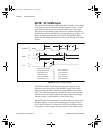
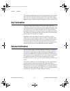
Figure 4-31 shows the timing requirements for the GPCTR1_OUT
signal.
Figure 4-31. GPCTR1_OUT Signal Timing
Rising-edge
polarity
Falling-edge
polarity
t
w
t
w
= 10 ns minimum
GPCTR1_SOURCE
GPCTR1_OUT
GPCTR1_OUT
(Toggle output on TC)
(Pulse on TC)
TC
PCI_E.book Page 33 Thursday, June 25, 1998 12:55 PM