


Chapter 4 Signal Connections
PCI-6110E/6111E User Manual 4-26
©
National Instruments Corporation
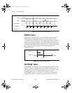
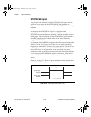
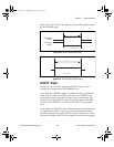
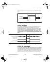
The maximum allowed frequency is 20 MHz, with a minimum pulse
width of 23 ns high or low. There is no minimum frequency limitation.
Either the 20 MHz or 100 kHz internal timebase generates the
SISOURCE signal unless you select some external source. Figure 4-20
shows the timing requirements for the SISOURCE signal.
Figure 4-20. SISOURCE Signal Timing
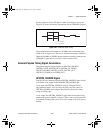
Waveform Generation Timing Connections
The analog group defined for the 611
X
E board is controlled by
WFTRIG, UPDATE*, and UISOURCE.
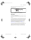
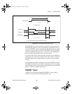
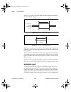
WFTRIG Signal
Any PFI pin can externally input the WFTRIG signal, which is available
as an output on the PFI6/WFTRIG pin.
As an input, the WFTRIG signal is configured in the edge-detection
mode. You can select any PFI pin as the source for WFTRIG and
configure the polarity selection for either rising or falling edge. The
selected edge of the WFTRIG signal starts the waveform generation for
the DACs. The update interval (UI) counter is started if you select
internally generated UPDATE*.
As an output, the WFTRIG signal reflects the trigger that initiates
waveform generation. This is true even if the waveform generation is
being externally triggered by another PFI. The output is an active high
pulse with a pulse width of 25 to 50 ns. This output is set to tri-state at
startup.
t
p
t
w
t
w
t
p
t
w
= 50 ns minimum
= 23 ns minimum
PCI_E.book Page 26 Thursday, June 25, 1998 12:55 PM