


Chapter 4 Signal Connections
PCI-6110E/6111E User Manual 4-12
©
National Instruments Corporation
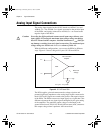
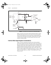
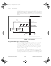
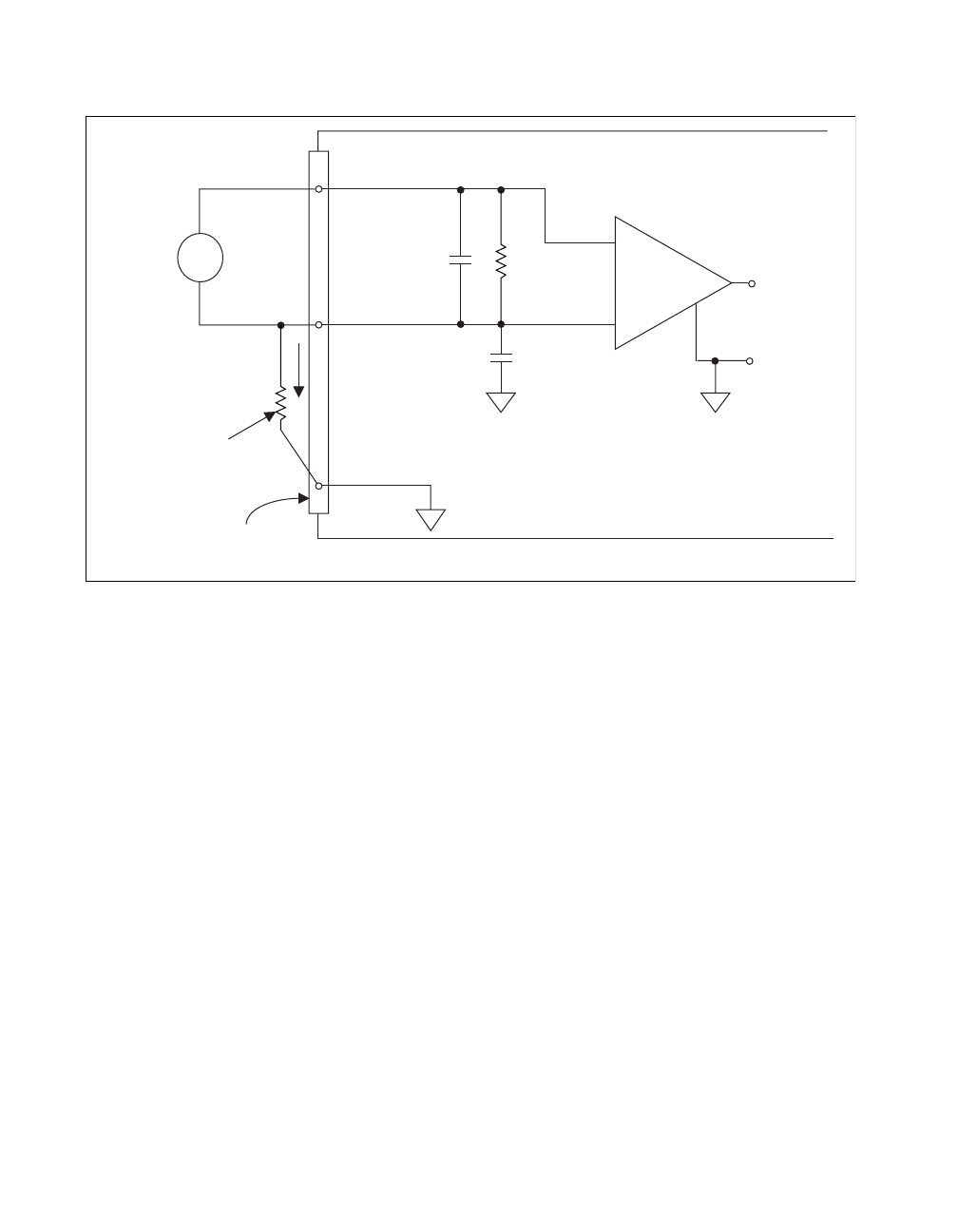
Figure 4-4. Differential Input Connections for Nonreferenced Signals
Figure 4-4 shows a bias resistor connected between ACH0 – and the
floating signal source ground. If you do not use the resistor and the
source is truly floating, the source is not likely to remain within the
common-mode signal range of the PGIA, and the PGIA will saturate,
causing erroneous readings. You must reference the source to the
respective channel ground.
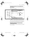
Common-Mode Signal Rejection Considerations
Figure 4-3 shows connections for signal sources that are already
referenced to some ground point with respect to the 611
X
E
board. In
this case, the PGIA can reject any voltage caused by ground potential
differences between the signal source and the board. In addition, with
differential input connections, the PGIA can reject common-mode noise
pickup in the leads connecting the signal sources to the board. The
PGIA can reject common-mode signals as long as V
+
in
and V
-
in
(input
signals) are both within ±11 V of the channel ground, for gain ≥ 1. For
gain <1, the input signals, for ACHO +, can be within ±42 V of the
channel ground.
+
-
+
Floating
Signal
Source
Instrumentation
Amplifier
V
m
Measured
Voltage
-
V
S
-
+
I/O Connector
ACH0GND
Bias
Current
Return
Paths
ACH0-
ACH0+
ACH0 Connections Shown
PGIA
1MΩ100pf
10nf
Bias
Resistor
(see text)
PCI_E.book Page 12 Thursday, June 25, 1998 12:55 PM