


Chapter 3 Hardware Overview
©
National Instruments Corporation 3-13 PCI-6110E/6111E User Manual
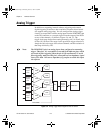
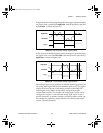
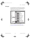
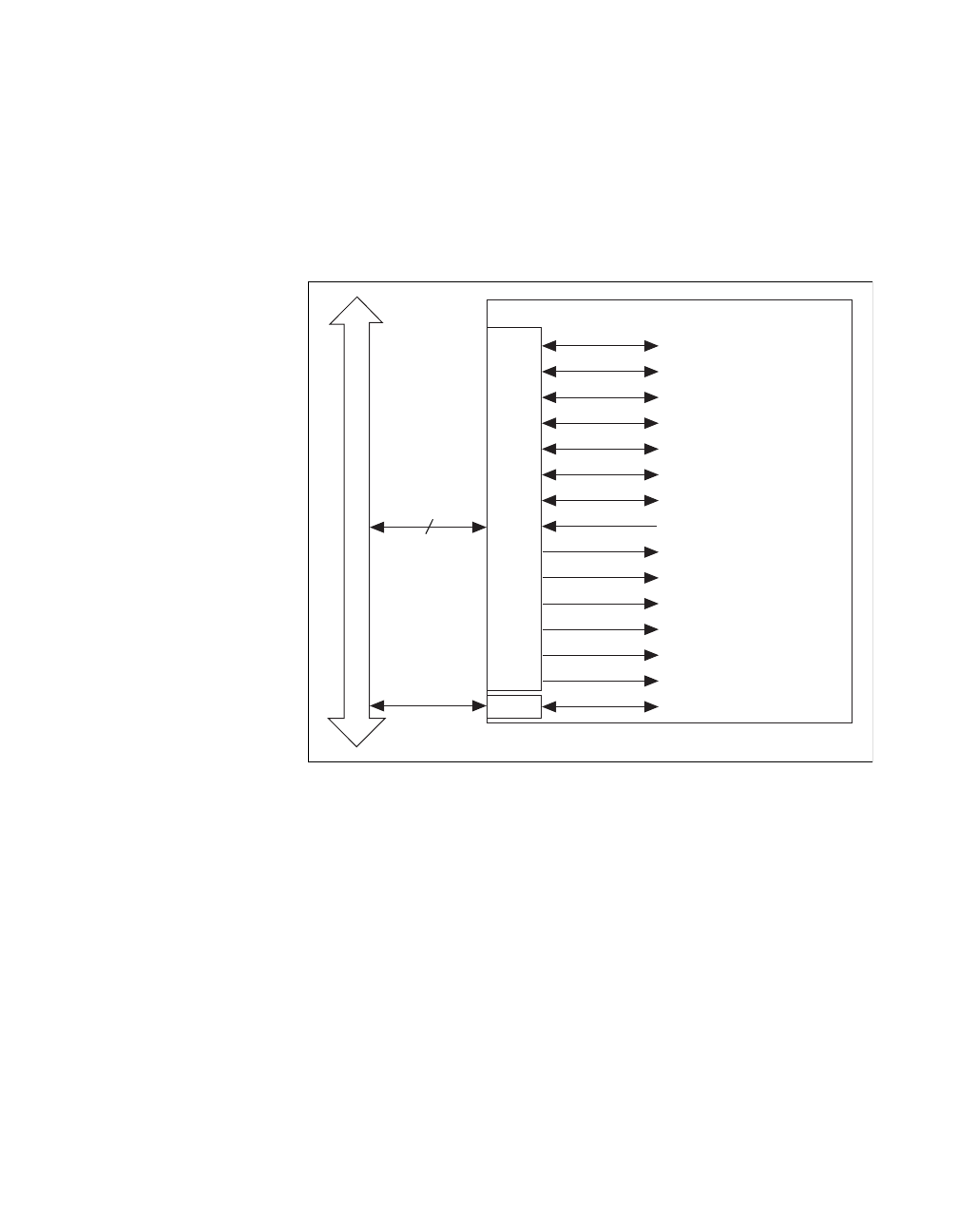
RTSI Triggers
The seven RTSI trigger lines on the RTSI bus provide a very flexible
interconnection scheme for the 611
X
E board sharing the RTSI bus.
These bidirectional lines can drive any of eight timing signals onto the
RTSI bus and can receive any of these timing signals. This signal
connection scheme is shown in Figure3-12.
Figure 3-12.
RTSI Bus Signal Connection
Refer to the
Timing Connections
section of Chapter4,
Signal
Connections
, for a description of the signals shown in Figure3-12.
RTSI Bus Connector
switch
RTSI Switch
Clock
Trigger
7
DAQ-STC
TRIG1
TRIG2
CONVERT*
UPDATE*
WFTRIG
GPCTR0_SOURCE
GPCTR0_GATE
GPCTR0_OUT
STARTSCAN
AIGATE
SISOURCE
UISOURCE
GPCTR1_SOURCE
GPCTR1_GATE
RTSI_OSC (20 MHz)
PCI_E.book Page 13 Thursday, June 25, 1998 12:55 PM