


Chapter 4 Signal Connections
PCI-6110E/6111E User Manual 4-16
©
National Instruments Corporation
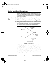
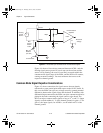
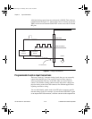
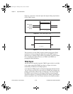
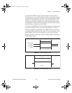
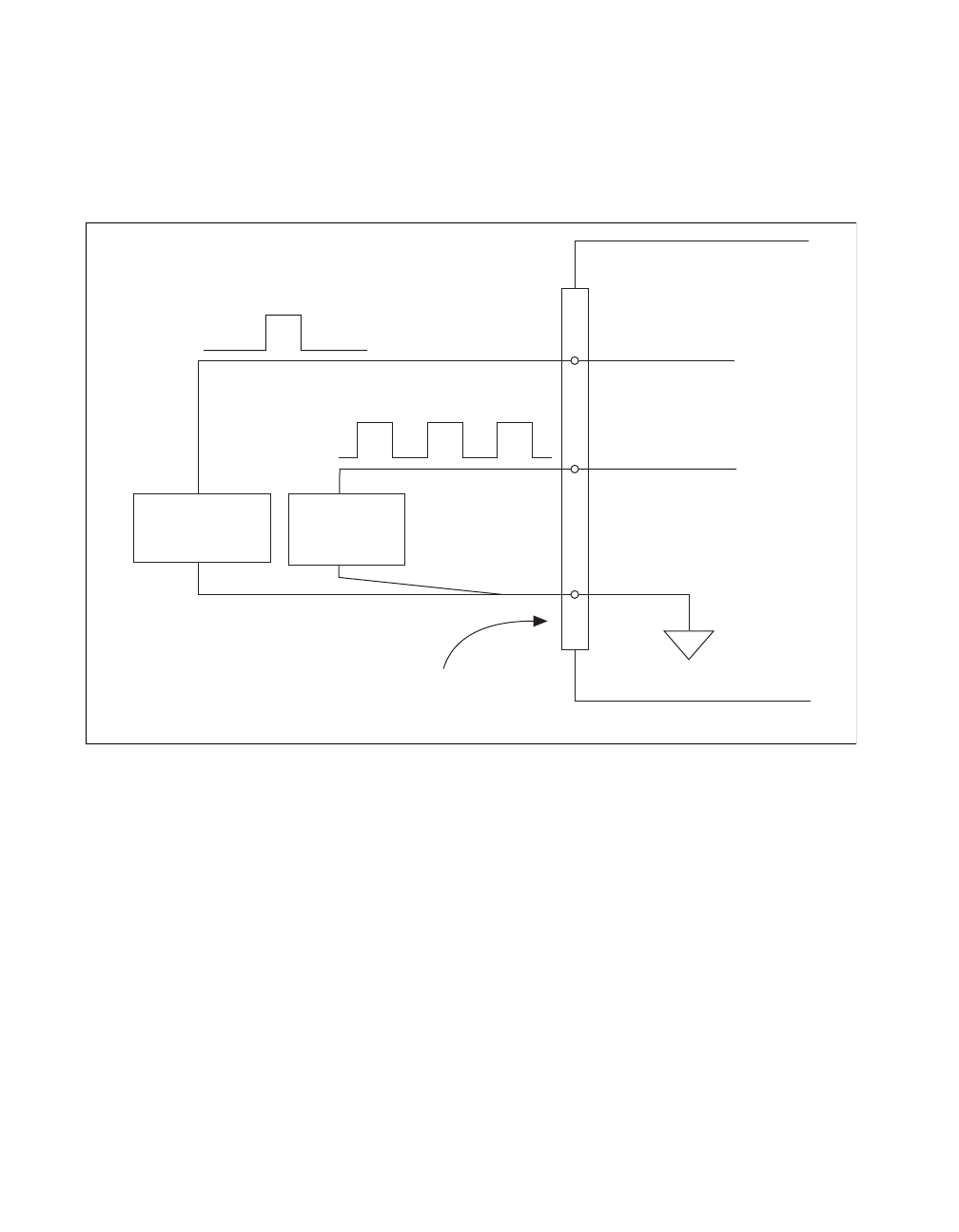
All digital timing connections are referenced to DGND. This reference
is demonstrated in Figure 4-7, which shows how to connect an external
TRIG1 source and an external CONVERT* source to two 611
X
E board
PFI pins.
Figure 4-7. Timing I/O Connections
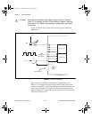
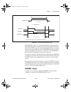
Programmable Function Input Connections
There are a total of 13 internal timing signals that you can externally
control from the PFI pins. The source for each of these signals is
software-selectable from any of the PFIs when you want external
control. This flexible routing scheme reduces the need to change the
physical wiring to the board I/O connector for different applications
requiring alternative wiring.
You can individually enable each of the PFI pins to output a specific
internal timing signal. For example, if you need the CONVERT* signal
as an output on the I/O connector, software can turn on the output driver
TRIG1
Source
DGND
PFI0/TRIG1
PFI2/CONVERT*
CONVERT*
Source
I/O Connector
611
X
E Board
PCI_E.book Page 16 Thursday, June 25, 1998 12:55 PM