


Chapter 4 Signal Connections
©
National Instruments Corporation 4-35 PCI-6110E/6111E User Manual
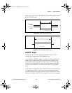
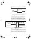
low) for at least 10 ns before the rising or falling edge of a source signal
for the gate to take effect at that source edge, as shown by t
gsu
and t
gh
in Figure 4-32. The gate signal is not required to be held after the active
edge of the source signal.
If you use an internal timebase clock, the gate signal cannot be
synchronized with the clock. In this case, gates applied close to a source
edge take effect either on that source edge or on the next one. This
arrangement results in an uncertainty of one source clock period with
respect to unsynchronized gating sources.
The OUT output timing parameters are referenced to the signal at the
SOURCE input or to one of the internally generated clock signals on the
611
X
E board. Figure 4-32 shows the OUT signal referenced to the
rising edge of a source signal. Any OUT signal state changes occur
within 80 ns after the rising or falling edge of the source signal.
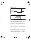
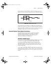
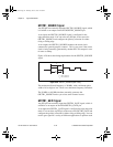
FREQ_OUT Signal
This signal is available only as an output on the FREQ_OUT pin. The
frequency generator for the 611
X
E board outputs the FREQ_OUT pin.
The frequency generator is a 4-bit counter that can divide its input clock
by the numbers 1 through 16. The input clock of the frequency
generator is software-selectable from the internal 10 MHz and 100 kHz
timebases. The output polarity is software selectable. This output is set
to tri-state at startup.
Field Wiring Considerations
Environmental noise can seriously affect the accuracy of measurements
made with the 611
X
E board if you do not take proper care when
running signal wires between signal sources and the board. The
following recommendations apply mainly to analog input signal routing
to the board, although they also apply to signal routing in general.
Minimize noise pickup and maximize measurement accuracy by taking
the following precautions:
• Use differential analog input connections to reject common-mode
noise.
• Use individually shielded, twisted-pair wires to connect analog
input signals to the board. With this type of wire, the signals
attached to the ACH+ and ACH– inputs are twisted together and
then covered with a shield. You then connect this shield only at one
PCI_E.book Page 35 Thursday, June 25, 1998 12:55 PM