


3-2 Disassembly and Reassembly
This section contains step-by-step disassembly procedures for the system unit. A
simplified disassembly illustration is provided with most procedures. Section 5
includes a parts list and an illustrated parts breakdown showing an exploded
view of the system.
A Phillips-head screwdriver is the only required tool. For complete disassembly
of the system unit, follow the disassembly order listed in the following table. To
reassemble, follow the table and procedures in reverse order. Where reassembly
is not readily apparent, reassembly procedures are provided.
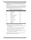
PowerMate VT 300i Series Disassembly Sequence
Sequence Part Name See Page
1 System unit covers 3-3
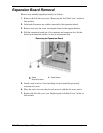
2 Expansion board 3-8
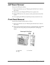
3 AGP Board 3-9
4 Front panel 3-9
5 Blank panel and metal shield 3-10
6 DIMM memory module 3-11
7 Processor cartridge 3-11
8 5 1/4-inch device 3-18
9 3 1/2-inch hard drive 3-19
10 3 1/2-inch diskette drive 3-19
11 Power supply 3-21
12 System board 3-22
13 CMOS battery 3-23
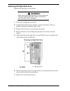
When disassembling the system unit, follow these general rules.
Before opening the system or handling boards or chips, touch the frame
to discharge static.
Disconnect all peripherals before disassembling the system unit.
Do not disassemble parts other than those specified in the procedure.
All screws are Phillips-head, unless otherwise specified.
Label any connector before removing it. Note where the connector goes
and in what position it was installed.
On completion of any reassembly, perform a power-on test. If a fault occurs,
verify that the reassembly was performed correctly.