


4-2 System Board
This section describes the locations of connectors, jumpers, and sockets on the
system board, including external cable connectors, internal board connectors,
jumper locations, and upgrade sockets.
Included in this section are procedures for setting jumpers on the system board
and a DIMM memory upgrade path for the DIMM sockets. Also included are
descriptions of system board components, system memory map, and I/O
addresses.
Connectors, Jumpers, and Sockets
The following paragraphs describe the system board external cable connector
locations, internal board connector locations, jumper locations, and upgrade
sockets. Included are procedures for setting jumpers on the system board and a
table showing the upgrade path for the DIMM sockets.
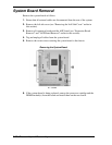
External Cable Connectors
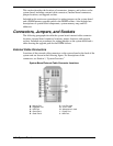
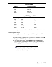
Locations of the external cable connectors on the system board at the back of the
system unit are shown in the following figure. For descriptions of the
connectors, see Section 1, “System Overview.”
System Board External Cable Connector Locations
A – Mouse Port F – Line Out Jack
B – Keyboard Port G – Line In Jack
C – USB Port H – Microphone In Jack
D – Serial Port 1 I – Printer Port
E – Serial Port 2 J – MIDI Port