


viii Contents
List of Figures
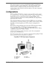
PowerMate VT 300i Series System Components................................................................................. 1-2
PowerMate VT 300i Series System Front View................................................................................... 1-4
PowerMate VT 300i Series System Rear View.................................................................................... 1-6
Inside the System................................................................................................................................ 1-7
Processor/Bus Speed Jumper Block SW1 Settings............................................................................... 2-5
Setup Main Menu ............................................................................................................................... 2-9
Welcome screen ............................................................................................................................... 2-20
Removing the Left Side Cover ............................................................................................................ 3-4
Replacing the Left Side Cover............................................................................................................. 3-5
Removing the Right Side Cover.......................................................................................................... 3-6
Replacing the Right Side Cover .......................................................................................................... 3-7
Removing an Expansion Board........................................................................................................... 3-8
Removing the Front Panel................................................................................................................... 3-9
Removing the Blank Panel................................................................................................................ 3-10
Removing a DIMM Module.............................................................................................................. 3-11
Removing the Celeron or Pentium III Processor Cartridge................................................................. 3-13
Installing the Celeron or Pentium III Processor Cartridge .................................................................. 3-14
Removing the Pentium II Processor Cartridge................................................................................... 3-16
Installing the Pentium II Processor Cartridge..................................................................................... 3-17
Removing a 5 1/4-Inch Device.......................................................................................................... 3-19
Removing the Hard Drive................................................................................................................. 3-20
Removing the Power Supply............................................................................................................. 3-21
Removing the System Board............................................................................................................. 3-22
Locating the Battery.......................................................................................................................... 3-23
Removing the Battery....................................................................................................................... 3-24
System Board External Cable Connector Locations............................................................................. 4-2
System Board Internal Connector and Socket Locations ...................................................................... 4-3
Locating System Board Jumpers ......................................................................................................... 4-4
Processor Jumper Settings................................................................................................................... 4-5
PowerMate VT 300i Series Computer Illustrated Parts Breakdown...................................................... 5-5
Removing the Mouse Ball Cover......................................................................................................... 6-3
List of Tables
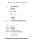
PowerMate VT 300i Series System Configuration............................................................................... 1-3
System Components ........................................................................................................................... 1-9
Interrupt Level Assignments ............................................................................................................... 2-3
Parallel Port Interrupts........................................................................................................................ 2-3
Serial Port 1 and Serial Port 2 Interrupts.............................................................................................. 2-4
Power On Mode Jumper JP1 Settings.................................................................................................. 2-6
Clear CMOS Jumper JBAT1 Settings.................................................................................................. 2-6
Wake-On LAN Jumper JWOL Settings............................................................................................... 2-6
Maxtor IDE Hard Drive Jumper Settings............................................................................................. 2-7
Seagate IDE Hard Drive Jumper Settings............................................................................................ 2-7
NEC 32X CD-ROM Drive Jumper Settings......................................................................................... 2-7
Lite-On 32X CD-ROM Drive Jumper Settings.................................................................................... 2-8
Zip Drive Jumper Settings .................................................................................................................. 2-8
Tape Backup Unit Jumper Settings...................................................................................................... 2-8
Navigation Keys............................................................................................................................... 2-10
Main Menu Items ............................................................................................................................. 2-10
Advanced Menu - Advanced CMOS Setup........................................................................................ 2-13
Advanced Menu - Advanced Chipset Setup....................................................................................... 2-14
Advanced Menu - Power Management Setup .................................................................................... 2-14
Advanced Menu - PCI/Plug and Play Setup....................................................................................... 2-16
Advanced Menu - Peripheral Setup................................................................................................... 2-16
Advanced Menu - Change Language Setting..................................................................................... 2-17
Security Menu Items......................................................................................................................... 2-17
Exit Menu Items............................................................................................................................... 2-18